

The Cassini 16 Infrastructure's manipulator tower uses a motor and control PCB to raise and lower the testhead. These instructions detail how to remove the access panel and replace the motor. Contact Support ([email protected]) for specific instructions for diagnosing or replacing malfunctioning items. The motor's control board must be programmed at the factory.
Note: Please provide RI a clear picture of the motor and control board when requesting hardware. Some internal revisions may require different hardware. These instructions may apply to R18568A0 thru RI8568B1.
Replacement Hardware provided by RI:
Motor and Control Board - MSV0HM5A (Assembly with Motor MM4C506A, Harness MKNN441C, Mounting Hardware + Allen wrench)
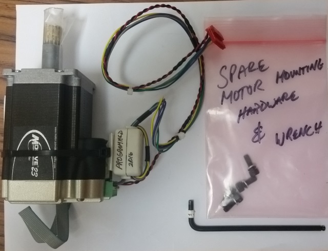
Additional Tools Needed:
#4 Allen Wrench (pictured above)
#1 Philips Screwdriver (Panels)
Electrical Shock Hazards
There are NO electrical shock hazards from any of the exposed electrical connections on the test head or on any surface of the system. The system uses 48 volts or less and shock hazards are typically designated as to 50 volts or higher. No high-voltage cables or connections are exposed at any time during operations or when moving the system. Fixtures and Tester Instrument Modules (TIMs) can be safely removed "hot" without disconnecting power without damaging the equipment or exposing live connections to the operator. The system is equipped with an Emergency Off (EMO) button that instantly disables all 48 volt connections.
The System Controller MUST ALWAYS be properly powered down BEFORE switching off any breakers. The "Main Breaker" is used to disconnect all electrical connections and can be switched "Off" before performing any infrastructure maintenance that requires tools to remove protective metal covers. The side breakers labeled "TIM Front", "TIM Rear", "Head" or "Mainframe" can be switched "Off" before opening specific service panels.
Cassini 16 Motor Replacement
- IMPORTANT: POWER DOWN THE SYSTEM CONTROLLER AND REMOVE ALL TIMS BEFORE DISASSEMBLING THE FRONT ACCESS PANEL!
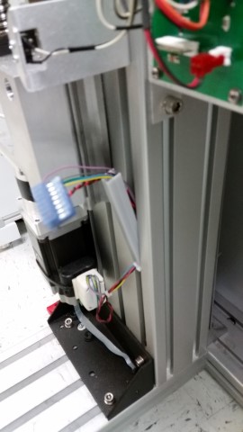
- Rotate the top of the Testhead away and unscrew the Cassini 16 front panel and remove.
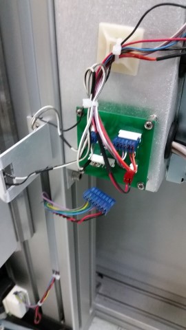
- Unplug the 8-pin motor connector at the motor driver PCB, and pry out the plastic wire channel cover as shown.
- Using a 4mm ball-end allen wrench, remove the 4 screws (with washers) securing the motor.
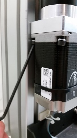
- Lower the motor and remove.
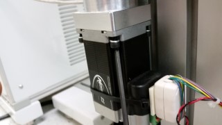
- Remove the plastic cover to the new motor's gear. The gear is lubricated to aid in installation and operation.
- Carefully install the new motor and reconnect in reverse order (you may need to rotate the motor slightly as you install it, to align the gear splines, so that you can slide it in).
- Package the old motor, protecting the gears, in the same box and return to RI for inspection. Clearly mark the RMA number on the shipping material.
- Restart the tester and verify proper lift operation.
- Reattach the front panel.