

All the RI ATE Systems are synchronous, integrated systems that allow control over all the tester functions to a resolution of 1uSec. Using the Pre and Post measure group functions, the application developer can control the timing of the DC supplies, DC measurements and RF measurements to implement Pulsed measurements for applications such as GSM.
The GSM mobile radio system utilizes a time segmented scheme, with an on time of 577uSec and a duty cycle of 1/8. An RI ATE System is typically called upon to produce a Voltage for that duration and repetition rate, while measuring Current and RF power during the pulse. This is easily implemented using the Pre and Post Measure groups. DC current pulse profiling as well as pulse power averaged over a number of cycles are typical measurements.
Current Measurement with Pulsed DC
Here is a measurement panel measuring current at 200 uSeconds after the beginning of a voltage pulse.
Current Measurement with Pulsed DC (continued)
There are several things to be aware of.
1.) Do not hot switch the Power VI supplies by switching from Off to ON under load or vice versa. The proper approach is to move the tester power supply from 0 to 3 V. This does not actuate the on off/relay in the Power VI. Insure that the supply is off before this panel by paying careful attention to the Connect Sequence, Disconnect Settings and Global/Section Defaults. An example is in the attached test plan.
2.) The measurement of current takes a finite amount of time. 1 average takes approx 80usec. In this case the pulse would turn off in 280 uSec. 200 from the delay, and 80 from the measurement. FYI, 16 averages takes approx. 250uSec., 8 averages approx.160uSec.
3.)You can verify the timings with an Oscilloscope and the timing tags in the "Delta Settings" view.
RF Measurement During a DC Pulse, GSM Rate
The same principles apply to the measurement of RF during the same pulse. Be aware that the RF measurement takes longer than the DC, but an 8 average measurement still fits easily in the 577uSec pulse width. In addition. It is sometimes required to make the power measurement over a number of successive pulses and obtain an average. To implement this, the Repeat and Post Measure buttons are added to the earlier approach.
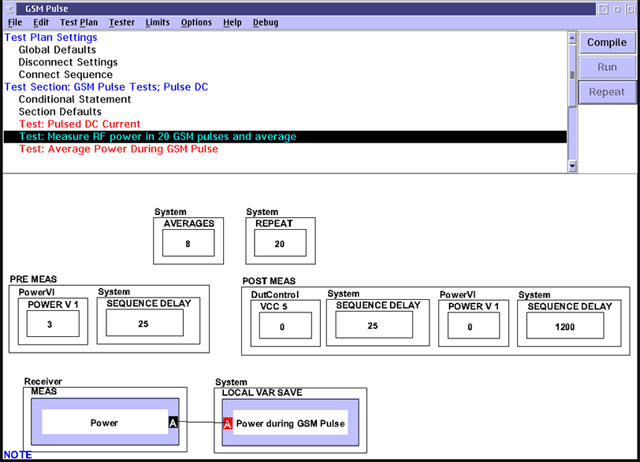
Please note:
1.) The initial 25 uSec sequence delay, 8 average RF measurement, and following 25 uSec sequence delay takes approximately 577 uSec.
2.) The VCC5=0 is a "dummy" button. It does not change anything, but gives the second 25 uSec sequence delay something to associate to, other wise it would be ignored.
3.) The final sequence delay of 1200 uSec, along with the testers overhead of resetting up the measurement for the repeat, takes the balance of the 4.6 mSec cycle. This 1200 uSec number was established using an Oscilloscope and iterating to get the proper period.
4.) After 20 repeats the data in the local variable is averaged to give the average pulse power.
Here is the example test plan