

Purpose: To describe the RIK0053B Fixture Cbit Controller and its use. (Note: revA had QTY 2 modules)
The standard fixture control circuitry includes eight Cbits that can be used to control or drive
devices needed to route or otherwise process signals to the DUT. In some instances more than
eight are required. It is for this reason that ROOS Instruments developed the RIK0053A Fixture Cbit Controller.
The following is a description with programming notes of this fixture module.
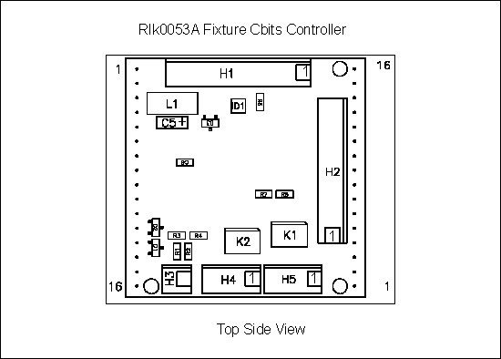
Top View:
Header Pin Out:
Header # | Pin# | Function |
1 | 1 | Cbit 8 |
1 | 2 | Drive voltage |
1 | 3 | Cbit 7 |
1 | 4 | Drive voltage |
1 | 5 | Cbit 6 |
1 | 6 | Drive voltage |
1 | 7 | Cbit 5 |
1 | 8 | Drive voltage |
1 | 9 | Drive Voltage Input |
1 | 10 | Gnd Connect |
2 | 1 | Cbit 1 |
2 | 2 | Drive voltage |
2 | 3 | Cbit 2 |
2 | 4 | Drive voltage |
2 | 5 | Cbit 3 |
2 | 6 | Drive voltage |
2 | 7 | Cbit 4 |
2 | 8 | Drive voltage |
2 | 9 | Drive Voltage Input |
2 | 10 | Gnd Connect |
Header # | Pin# | Function |
4 | 1 | Opto2 Pin1 |
4 | 2 | Opto2 Pin2 |
4 | 3 | Opto2 +15 |
4 | 4 | Opto2 GND |
5 | 1 | Opto1 Pin1 |
5 | 2 | Opto1 Pin2 |
5 | 3 | Opto1 +15 |
5 | 4 | Opto1 GND |
Note:
Pins 2,4,6,8, and 9 on Headers 1&2 are common.
H4 and H5 each connect to an AQV212 opto relay wired for bidirectional use. (GND and +15). Used to drive noise sources mainly. 60V 550mA
H3 is a serial number read.
Fixture requirements:
1. Smart Carrier.
2. Press in connector strips ( 16 pin ) installed at desired module locations ( M1 - M16 on 2AC1), (M1-M8 on 4AV1), (M1-MA on 65A1).
3. Bench Top DC Voltage Requirements: +5V / +12V
Cbits Available:
1. Standard Cbit 1 - 3 on 2AC and Cbit 1- 8 on all other carrirer boards.
2. Eight open collector Cbits per Switch Driver Module plus two optical Cbits.
Coding Requirements:
Fixture Carrier 2AC1 Position# | 12RF SquareDUT Fixture Carrier 4VA1 Position# | Fixture Carrier 65A1 Position# | Smart Carrier Module# | RIFL Carrier Module# |
M1 | M1 | M1 | M1 | M1 |
M2 | M2 | M2 | M2 | M2 |
M3 | M3 | M3 | M3 | M3 |
M4 | M4 | M4 | M4 | M4 |
M13 | M5 | M5 | M5 | M5 |
M14 | M6 | M6 | M6 | M6 |
M15 | M7 | M7 | M7 | M7 |
M16 | M8 | M8 | M8 | M8 |
M9,M10 not supported | M9 | M9 | ||
MA | MA | |||
MB | ||||
MC | ||||
MD |
| Part # | Description | Carrier PCB # | ||
| RIK0013B | Passive Carrier w/o harness, RI7100A, 12 RF Top | 4VB2 | ||
| RIK0014B | Active Carrier, RI7100A, 12 RF Top | 4BV1 | ||
| RIK0084A | Active Carrier, RI7100A, 20 RF Fixture | 65A1 | ||
| RIK0160A | Active Carrier, For Matrix Top, NO-RIFL | 6KA3 | ||
| RIK0175A | Active Carrier & Harness, 1x5 slot, RIFL | B7A1 | ||
| RIK0200A | RIFL Carrier, Cassini, Matrix Top, 13 Modules | 6KB2 | ||
| RIK0236A | Expansion RIFL Carrier, 1x5 slot, Bus Cable | B7A2 |
1. When writing to a standard Cbit ( found on the fixture carrier board ) the format is of CXY
C = C, X = control bit used (only 1-3 are usable on the smart carrier of type Y0002AC), Y = 1 or 0.
- Ex. C20 Sets the standard Cbit#2 low.
2. When writing to a Smart Carrier Cbit Module the format is of M#AXXXXXXXX. M = M, # = Module number being written to, A = A, X = 1 or 0. All bits must be defined as 1 or 0
Ex. M4A00000010 Writes to Smart Module #4 and sets bit#2 low.
3. When combining standard Cbit commands and Smart Module commands place the standard commands first.
- Ex. C10M4A00111000 Sets standard Cbit#1 low. It then writes to Smart Module #4 and sets the appropriate Cbits for the 70dB setting on the attenuator.
4. When combining to Smart Module commands combine them in one long string.
- Ex. M4A00000001M8A00000000 Writes to module #4 and sets its bit#1 low. It then writes to module #8 and sets all bits high.
5. When using the Smart Carrier Cbit Module to control a programmable attenuator ALL bits associated with the attenuator need to be driven either high or low.
Ex. M8A00111000 Writes to Smart Module #8 and controls Cbits 8-3 to set the atten to 70dB.
Note: Observe that the 1 = High on a standard Cbit while 1 = Low on a Smart Module Cbit.
Carrier Opto Cbits Programming:
1. When writing to a Opto Cbit the format is of S#1XX1
S = S, # = Module number being written to, X = 1, X, or 0.
0 = closed (0V) and 1 = open (3.8V)
Bit position = S# DS1 DS2 DS3 DS4
Ex: S81100 Writes to smart module #8 and controls Opto1 to connect Pin1 & Pin2
Software Fixture Considerations:
1. When creating the software fixture, ALL Cbits should be given a default state other than "X". Define these states on the first path entry of the software fixture.
Ex. DutRf2 Rf2 default M4A00000011M8A00000011.
Note: If this is not done then it is possible that an error will occur and appear in the programmer message window.
"Error undefined bit in fixture module M4 value 0000001X"
The X defines in this case the Cbit that needs a default state.