A very fast and accurate method for measuring I/Q Demodulators is to use the RI ATEs receiver and an RI RF MMIC switch in the Test Fixture to measure the Amplitude Balance and Phase Balance directly. This process is usable even for "ZeroIF" radios that typically are tested at output frequencies below 100kHz. This frequency can be below the capability of most of the RF tester resources, and typically has been measured with a "Mixed Signal" resource such as a digitizer. However low frequency sinusoids are actually measured more effectively using the Low frequency path of the Receiver. This path allows 0.1 degree repeatability for even these measurements in a fraction of the time necessary for a digitizer to the achieve the same accuracy.
For Tester Considerations using the low frequency receiver path ( AKA RF4) please see RF4, Low Frequency Receive Considerations and Calibration.
The general fixturing approach is to take the demodulators I and Q output and run them in to a RI MMIC SPDT RF switch controlled by C-Bit1. For additional information on creating fixtures and calibration for this type of measurement see AC Fixture Calibrations.
Note:
1.) Cbit 1 must be used to utilize the special Receiver switched I & Q measurement button. Cbit 1 on the Smart Carrier is valid as well
2.) The normally closed throw of the switch goes to the I path
3.) RF4 has special considerations for power that must be considered ( see RF4 in documentation)
4.) Many demodulators have differential outputs that may require an RiK buffer board and a special calibration
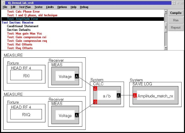
Amplitude Balance
For the amplitude balance measurements the simple approach of measuring the I path and Q path amplitude is just as repeatable as the sepcial Switched I & Q button method:
Phase Balance
Phase Balance measurements must utilize the specialty measurement "Switched IQ". The switched IQ approach controls the IQ switch (C-bit1) to measure the instantaneous phase difference between the I and Q channels. Measuring the difference between I and Q and then averaging allows the tester to greatly reduce any short term reference phase drift that would occur between the two measurements.
The switched IQ measurement is accessed by using a Receiver Measure button, right click, select Pick Meas, then select Switched I vs Q.
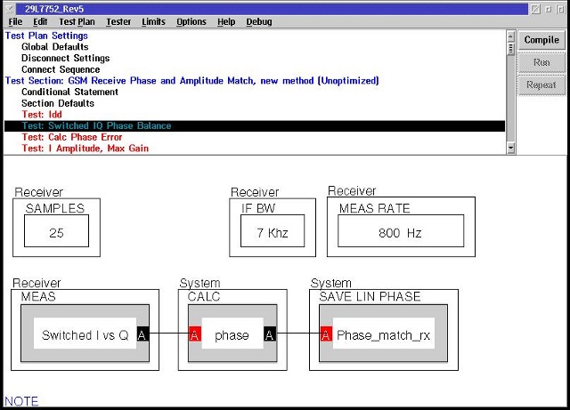
Things to Note:
1.) The Samples Button provides the averaging.
2.) The frequency range below 100kHz contains many different spurious signals. In some cases the Receiver IF BW must be 7kHz.
3.) IF the IFBW is 7kHz the Receiver Measure Rate button must be implemented. Just as in a spectrum analyzer when you narrow the IF the sweep rate slows down. Here using the 7kHz IF forces the reduction of the measure rate from the default of 20kHz to 800 Hz.
4.) If the 4 MHz BW is used the measure rate should be between 20kHz and 40kHz and the samples can be increased by the same ratio without affecting test time.
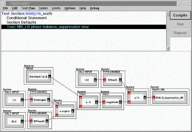
Receiver Error Vector Suppression:
The resultant magintude and phase of a demodulator composes an error vector. The magnitude of this vector can be compared to the ideal vector to calculate the Suppression term. Here in terms of power we have:
Where A is the Voltage Ratio of Q/I and Phi is the phase.
In terms of voltage we have: Where the denominator is simply:

Well the resultant of the Switched I/Q measurement is the Vector Ratio of Q to I:
So this complex calculation is simply implemented using the native complex mathematics of Ri Apps with this panel: