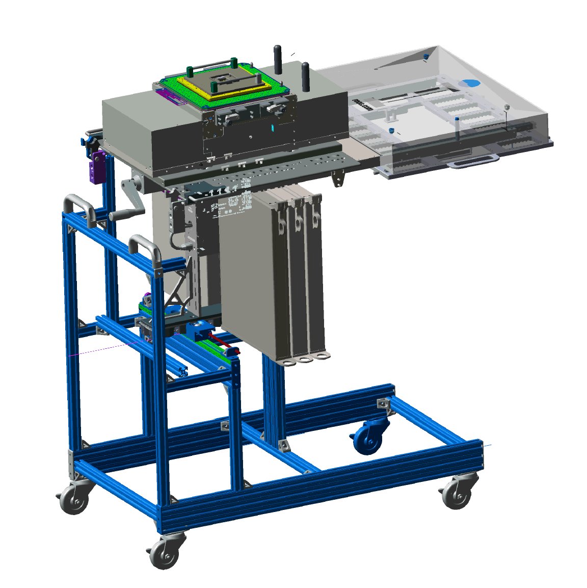
The RI8611A Cassini V93K CTH Infrastructure (Cassini Infrastructure) can be installed and removed with the MZYB336A Cart for Cassini V93K CTH Infrastructure. The methods for attaching and removing the RI8611A Cassini V93K CTH Infrastructure from the Advantest V93000 SoC Tester (Advantest V93000 Head) are detailed in the following text. These instructions assumes the Cassini V93K CTH Infrastructure has been setup and a Fixture attached.
Tools Needed:
- Torx T20 or T25 driver
- 9/16-in Wrench*
- Zip Ties for 48V Power Supply*
- Allen 4mm Ball end T-handle wrench*
*Optional to make adjustments
To Attach a RI8611A Cassini V93K CTH Infrastructure to Advantest V93000 SoC Tester:
- Position the MZYB336A Cart for Cassini V93K CTH Infrastructure near the Advantest V93000 head and position the head to prepare for docking.
- Inspect the Infrastructure and all connectors to the Advantest V93000 head for any signs damage. Look closely at pins and pin housings, as pins can sometimes get pushed down to far into the connector. Look for cleanliness and security of the Infrastructure and all switches & connectors. When cleaning the connectors, use compressed air to clean the connectors on the Infrastructure. Use an all purpose cleaner to clean the system. Its best to spray the cleaner directly onto a cloth to wipe down the Infrastructure vs. spraying the cleaner on the system.
- On the Advantest V93000 head, lock the floating base ring to minimize sagging due to the forward weight. (See Figure 2) Use a Torx T20 or T25 driver to loosen and move the locking tabs into position so that they are securing the ring. As illustrated in Figure 2a, if the tabs are in the unlocked position (red "X"), then loosen the screws and slide inward, then tighten to make them look like the green check mark.
- Position on the Advantest V93000 docking area by lining up the visible rollers of Infrastructure to slots on the back of the like the green lines show in Figure 3.
- Use the Advantest V93000 remote HARD DOCK button to activate the pneumatic rollers once the infrastructure is securely on the Advantest V93000 shown in Figure 1.
- Attach the external 48V Power Supply to the Advantest V93000 handle. Use zip ties to attach the 48v power supply brick to the handle of the Advantest V93000 as shown by blue arrows in Figure 4.
- Attach the AC Power cord to a 110V IEC Plug located on the resource ring on the back of the Advantest V93000, see the yellow arrow in Figure 5.
- (Optional) Plastic bars rest on the pucks of the Advantest V93000 have been adjusted at the factory so that the head will be level when resting on them. Use a smart phone level application to confirm. If the infrastructure is not level, then use an Allen 4mm ball end T-Handle wrench to loosen the 4 cap head screws (on each side purple arrows.) Use an assistant to lift the infrastructure with the screws loose while observing the level resting on the top plate. Once level, then the assistant should tighten all of the screws as shown in Figure 6.
- Connect the USB Command and Control cable from the RI8611A Infrastructure to an available USB port on the Advantest V93000 controller and continue with launching SmarTest 8 to Advantest specific instructions.
To Remove a RI8611A Cassini V93K CTH Infrastructure from Advantest V93000 SoC Tester:
- Disconnect the USB Command and Control cable from the RI8611A Infrastructure from the Advantest V93000 controller.
- Disconnect the AC Power cord from the 100V IEC Plug located on the resource ring on the back of the Advantest V93000, see the yellow arrow in Figure 6.
- Position the MZYB336A Cart for Cassini V93K CTH Infrastructure under the RI8611A Cassini V93K CTH Infrastructure and use the Advantest V93000 remote to move the test head DOWN onto the cart.
- Use the Advantest V93000 remote HARD UNDOCK button to activate the pneumatic rollers to release the RI8611A Infrastructure shown in Figure 1.
- Move the Cart with Infrastructure away from the Advantest test head.
- (Optional) On the Advantest V93000 head remote control, unlock the floating base ring. Use a Torx T20 or T25 driver to loosen and move the locking tabs into position so that they are no longer securing the ring as shown in "red X" in Figure 2a.
Figure 1: Advantest V93000 Head remote control

Figure 2: Location of the V93000 Floating Base Ring
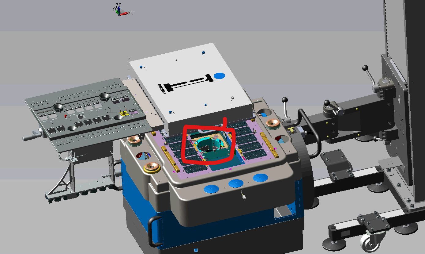
Figure 2a: Locking the V93000 Floating Base Ring (Red X is Unlocked, Green Check is locked)

Figure 2b: Locking the V93000 Floating Base Ring Photo

Figure 3: Align and Attach Infrastructure
Figure 4: Power Supply mounted to head

Figure 4b: Power Supply mounted to head, and USB Command and Control cable alternate angle

Figure 5: DC Power Plug for 48V Power Supply

Figure 6: Alignment Adjustments

Figure 7: To Adjust Advantest V93000 Manipulator Arm

Figure 8: Cart with V93K CTH Infrastructure attached to Head

Figure 9: Cart with Cassini V93K CTH Infrastructure