The Effective Receiver Bandwidth can be described as "For a given CW signal, over what range of Receiver frequencies will the Receiver respond to that signal" the converse is also valid, "Over what signal frequencies will a receiver at a fixed frequency respond ".
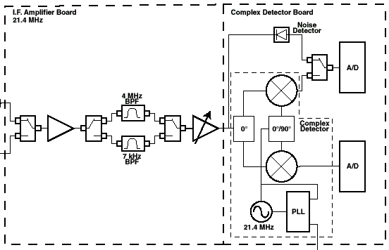
To understand how this operates it is instructive to look at the Receiver Block Diagram:

Any signal coming in to the Receiver is first limited by the IF filter, and the two filters are labeled by their 3dB bandwidths as shown, 5 MHz and 7 kHz respectfully. They have different shapes due to their design requirements. The 7 kHz option is a "high Q" 6 pole "brick wall" type of filter designed to separate a signal from another in close proximity. This filter has over 55 dB of rejection out of band with a +/- 3.75 kHz bandwidth. The 5 MHz option is a typical Gaussian filter design chosen to closely correlate to bench top Spectrum / Network Analyzers and to pass wide-band signals while rejecting the Receiver's LO, @ 21.4 MHz
After the IF Filter, then there are two different Receiver detection circuits. The Complex, or IQ detector has switchable additional filtering for a 3dB bandwidth of approx 200 kHz or 5 MHz respectfully.
The true Noise, or RMS detector has a bandwidth of 10's of MHz.
Receiver Noise Floor
1) The Noise Floor of the Receiver/Test Head combination ( in direct receive mode with 0 Rec Attn) is typically approx -150 dBm/Hz
2) The Noise Floor of the Receiver/Test Head combination ( in S-Parameter receive mode with 0 Rec Attn) is typically approx -124 dBm/Hz
3) The Noise Floor of the Receiver directly is typically approximately -120 dBm/Hz
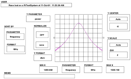
Following is a measurement of the effective Receiver bandwidth with the 5 MHz IF and the Complex Detector

Cascaded Effective Receiver Bandwidth
The Effective Receiver Bandwidth is the cascaded bandwidth of the IF Filter and then the appropriate Receiver.
Case 1) 7 kHz IF Filter; Either Detector: In this case the IF filter Dominates. Effective Bandwidth = 7 kHz (when measuring Noise type signals effective BW is approx the same as a Gaussian 10 kHz)
Case 2) 200 kHz IF Filter: This setting uses the 5 MHz IF filter; then a Complex Detector filter of 200kHz: In this case the Complex Detector filter is the limiting factor. Effective Bandwidth = 200 kHz (when measuring Noise type signals effective BW is approx the same as a Gaussian 250 kHz) NOTE: If using the RMS detector on this mode, the BW it will see is 5 MHz.
Case 3) 5 MHz IF; RMS Detectoror Complex Detector: In this case the 5 MHz IF Filter is the limiting Factor. Effective Bandwidth = 5 MHz (3dB) for both detectors.
Noise Bandwidth
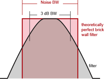
When you apply a continuous wave signal to a filter, the output power is dependent on where you are in the filter, full power in the middle, decreasing power at the sides. The bandwidth is the frequency range between the points where the power has dropped by 3 dB. But when you apply noise to a filter, the output power is the total integrated noise power through the filter. Since white noise is not a continuous wave signal, the concept of a 3 dB bandwidth for noise does not apply.
Accepted practice for noise is to use 'equivalent noise bandwidth', which is usually shortened to just 'noise bandwidth'. Equivalent noise bandwidth is defined as the bandwidth of a theoretically perfect brick wall filter that passes the same total integrated power as your filter. In other words, if you have a perfectly rectangular filter that passes the same noise power as your filter, they have the same noise bandwidth.

Noise bandwidth is ALWAYS wider than 3 dB bandwidth, because there's still filter left beyond the 3 dB points. The more poles the filter has, the steeper the sides, and the closer the noise bandwidth is to the 3 dB bandwidth. Since a perfectly rectangular filter is not actually realizable, the noise bandwidth is always wider than the 3 dB bandwidth.
With regards to the narrow filter in the RI testers, we call it a 7 kHz filter since its 3 dB bandwidth is approximately 7 kHz. There is some manufacturing process variation in building these narrow filters which results in the actual measured bandwidth being from 6 to 8 kHz But its noise bandwidth is always closer to 10 kHz. That's why we use 10 kHz in all our noise measurement calculations.
If you like calculations, here's a short article on noise bandwidth: http://www.k-state.edu/edl/docs/pubs/technical-resources/Technote1.pdf
Statistical means of controlling effective Resolution BW and Video BW
For those familiar with Spectrum Analyzer operation, the use of Vector averaging in the RI System Software can provide similar results as varying the Resolution BW and Video BW on a Spectrum Analyzer.
When averaging is employed on a Receiver Voltage Measurement, coherent signals are averaged to their RMS Voltage but non-coherent ( Noise ) signals that have varying phases average to zero, given enough time. This effect will lower the noise floor of a given measurement as the resolution BW adjustment would on a Spectrum Analyzer. The Receiver Sample Rate will set the A/D sample rate directly for the Averages to allow for anti-aliasing etc. and the number of averages will determine the amount of noise floor reduction realized. There is approximately a 1 to 1 correlation in measurement time to the number of Averages and the Sample Rate.
By using the Repeat function in a Test Panel and then later doing an Average math operation on the vector of data will provide similar results as to varying the Video BW on a Spectrum Analyzer.
This example testplan can be used to exercise the receiver's bandwidth, by varying the receiver measure mode (power. rms) and the IF bandwidth (7kHz, 5MHz)

