Serial bus reads with the RI8535 Digital TIM is similar to the method that is utilized by the Static Digital instrument in that there is both a Dut Defined and a Manual Mode. It is different in that it requires a Generic Read Address to be created in the DUT Control Editor, and it involves a pattern sequence to execute.
For the Dut Defined Mode:
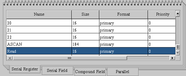
First create a Generic Read address. In this case it is 16 bit word called (surprisingly) Read.

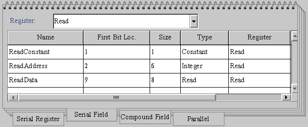
For the Fields, they are filled in the format required by the device. In this case bit 1 is the R/W bit.
Then we create a special field for the address, this is of the type integer, It will be filled in the test plan, to specify the desired register to read.
Secondly we create a field called Read Data, this is required to be of type "Read", this is the link that ties it to the read measure in the instrument.
Special note: It is possible to have more than one Read address in the case where the device might have registers of different sizes..

Tester View Panel:
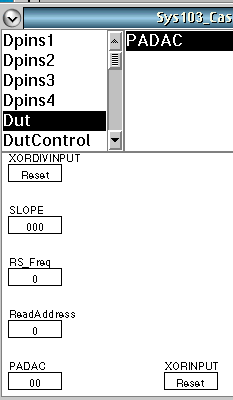
Looking in the Test Plan editor's button viewer display, there will now be a Dut Read Address button that will have been automatically created and that is what is used in your device Test Plan to control the read back.
Any other registers and or control bits can be programmed into the protocol aware user interface which will in turn generate more buttons to use within a Test Plan.

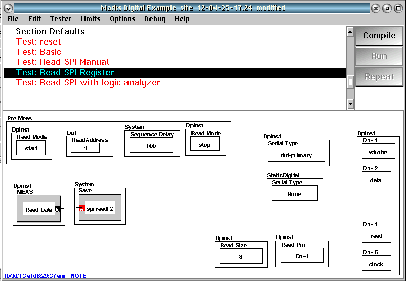
For the test plan we need to create the read sequence. Note the sequence delay needs to be long enough for the read. It is important (but probably should be in the global defaults) that the DPins serial type is "dut-Primary" but the Static Digital Serial Type is "None" Otherwise the static Digital Default (dut defined) will conflict.

Some additional notes that can be helpful:
Calculation to Extract Bits From a Serial Word
Device Definitions-Device Control-Serial and Parallel Ports

