Purpose: To describe how to measure the frequency of a free running VCO on the RI7100A using the Frequency Counter. This procedure is different than that used in the past where the VCO frequency was set and then the receiver frequency swept until maximum power is derived.
Theory: The basic idea is simple. Mix down into the 5-40MHz band the VCO frequency of interest. Use RF2 (SRC3) as the LO. Use the VCO output as the RF. Measure the IF output with the Oscope's frequency counter option.
Requires: Gen 3 (New OSCOPE), Option 005, 006, and 023 (BER).
| Option | Desciption |
| 005 | Time Domain Capability |
| 006 | Amplitude & Frequency Modulation On Src 1 |
| 023 | Bit Error Rate (BER) Measurement Capability |
Steps:
1. Determine by bench characterization approximate Vtune vs Freq at three points in band.
2. Set up the measurement using a Minicircuits ZEM 4300 or equivalent mixer.
RF2 (Src3) = LO set to 5dBm 10MHZ to 20MHz above approx. VCO freq.
VCO output = RF should have power level > - 15dBm
WF6 or 7 = IF output power > -15dBm
3. Set up Oscope time/div = .002. Use the MEASURE FREQ button found in the editor panel.
Test Considerations:
1. VCO warming over time needs to be taken under consideration during initial characterization.
This accounted for many KHz of error between soak values and instantaneous values.
2. .002 for a time/div setting gave the best resolution.
3. Test time was reduced to 8ms when pauses were removed.
4. Accuracy was somewhere within 10KHz. Long soak times (>30secs) were used to determine this.
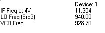
Results