

There are several methods for demodulator IQ balance measurements, with the RI test platform. One method uses the RF receiver to measure each signal. It is illustrated in the note, Demodulator Amplitude and Phase Balance Measurements using RF4 and "Switched IQ".
The alternate approach is to use the Tester's digitizers ( AKA WF6 and WF7) to capture the signals in the time domain. That is the subject of this note.
Each method has its own advantages. The Digitizer/Ellipse Fit method is fast. The Switched IQ method has the largest frequency range and amplitude range, as it uses the RF receiver.
The digitizer method utilizes a simultaneous capture of I and Q with the testers digitizers. Then instead of time averaging to get a precise value, we use an Ellipse fitting method to precisely and quickly establish the errors of the demodulator. The ellipse fit utilizes the a priori knowledge that I and Q are sinusoids, and if they are in perfect quadrature the amplitude of I and Q are the real and imaginary components of a circle. Any imperfection in magnitude and phase results in an ellipse. From a measurement perspective, the effect of individual sample errors are reduced in that the samples are fit to a sinusoid, In effect the errors are averaged across time.
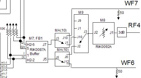
From a several fixture considerations to be addressed. Here is an example fixture block diagram. This configuration will support both the Switched IQ and the digitizer/Ellipse Fit approach.
Here is an example measurement panel:
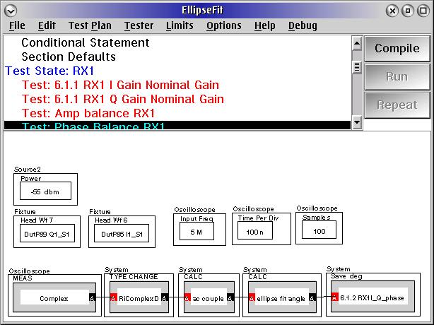
1.) In order to get a good measurement the voltage levels at the input of the scope should be relatively close to the scopes' full scale. (Approx 0.3 to 0.6V) You can see this by stopping at a break point pulling up the scope controller, Measure Both, and look at Real1 and Real2 (WF6 and 7). You can see exactly the data that is captured. One can then ramp the source power, to see the range etc.....
2.) The scope needs to know the input frequency so that it can deal with the calculations properly. In this case I have 100 nSec time per division. (That means that the time capture is 10X that, 10 divs on the screen or 1 uSec). So for a 5 MHz wave that gives us 5 cycles. Across that 5 cycles we get 100 points or 20 per. That is a good set up for precise measurements.
3.) The measurement needs to be mathematically "AC Coupled" That eliminates the orthogonal contribution of DC offset errors. The AC Couple calculation simply adds up all values and subtracts the mean.
4.) The type change to RiComplexD is not required after patch level P21C.637