This document provides you with a step by step process for attaching a RI8611A Cassini V93K CTH Infrastructure to the Advantest V93000 SoC Tester.
Prepare the site for installation:
- Site Preparation Guidelines for RI8611A 93k Testhead Cassini Infrastructure
- Unpacking a RI8611A Cassini V93K CTH Infrastructure from Shipping Crate
Tools Needed: (Included in shipment)
- Torx T20 or T25 Screwdriver
- 9/16-in Wrench
- Zip Ties for 48V Power Supply
- Allen 4mm Ball end T-handle wrench
- #1 Philips Head Screwdriver
Assemble the Cassini V93K CTH Infrastructure:
- Unpack the crate removing the boxes of TIMs first. (See Figure 1)
- Next remove the RI8611A Infrastructure ( it is shipped upside down for safety), and moved it into position near the Advantest V93000 head while protecting the top with the packing foam. This requires two people to lift due to size and its center of gravity where the weight is located. (See Figure 2)
- Inspect the Infrastructure and all connectors to the Advantest V93000 head for any signs damage. Look closely at pins and pin housings. Pins can sometimes get pushed down to far into the connector. Look for cleanliness and security of the Infrastructure and all switches & connectors. When cleaning the connectors, use compressed air to clean the connectors on the Infrastructure. Use an all purpose cleaner to clean the system. Its best to spray the cleaner directly onto a cloth to wipe down the Infrastructure vs. spraying the cleaner on the system.
- On the Advantest V93000 head, lock the floating base ring to minimize sagging due to the forward weight. (See Figure 3) Locking the base requires a T20 or T25 torx. Loosen and move the locking tabs into position so that they are securing the ring. As illustrated in Figure 4, if the tabs are in the unlocked position (red X), then loosen the screws and slide inward, then tighten to make them look like the green check mark.
- Pick up the the RI8611A Infrastructure Assembly with two people, flip it over and install on the Advantest V93000 docking area by lining up the rollers of Infrastructure to slots on the back of the like the green lines show. Those rollers will be the only ones visible, but if you line them up you should be good with the rest. (See Figure 5)
- Use the Advantest V93000 remote to activate the pneumatic rollers by pressing the HARD Dock button once the infrastructure is "on" the Advantest V93000.
- Attach the Infrastructure Cover, if it is not already installed, as shown in Figure 5b. Remove the protective wrap.
- Verify that the bumper is approximately 1-3 mm away from the Advantest V93000 cover (See Figure 6, orange arrow). This bumper keeps the infrastructure from diving off when released unsupported. The distance has been pre-adjusted, but the bumper need to be moved using a 9/16 wrench (included in shipment) if the Advantest V93000 cover is different.
- Attach the external 48V Power Supply to the Advantest V93000 handle or install anywhere the customer prefers. Use Zip ties (included in shipment) to attach the 48v power supply brick to the handle of the Advantest V93000 as shown by blue arrows in Figure 6.
- Attach the AC Power cord to a 110V IEC Plug located on the resource ring on the back of the Advantest V93000, see the yellow arrow in Figure 7.
- (Optional) Plastic bars rest on the pucks of the Advantest V93000 have been adjusted at the factory so that the head will be level when resting on them. Use a Level to confirm (not provided, use smart phone level application). If the infrastructure is not level, then use an Allen 4mm ball end T-Handle wrench (included in shipment) to loosen the 4 cap head screws (on each side purple arrows.) Use an assistant to lift the infrastructure with the screws loose while observing the level resting on the top plate. Once level, then the assistant should tighten all of the screws.
- Install the TIM's into their assigned locations. Remember to check the connectors for any signs of damage to the pins or pin housings. Also check for cleanliness and security of the connectors.
- Connect the USB Command and Control cable from the RI8611A Infrastructure to an available USB port on the Advantest V93000 controller and continue with Launching SmarTest 8 to Advantest specific instructions.
- To adjust the Advantest V93000 manipulator arm, reference Figure 9:
- Up and down (Z-plane) is controlled with handle circled in yellow.
- Side to Side (X and Y-planes) arm movements is circled in Orange.
- Head rotation is the wheel circled in Pink.
WARNING! Fixture should NOT be attached to the Test Head while powering on the system.
The Test Fixture should not be connected when turning the Infrastructure "ON". It could be possible to damage the Fixture or device because the Controller has not yet reset the states of the Test Head.
The Fixture can be freely swapped while the system is idle or off, but a fixture should not be connected during start-up.
Figure 1: TIM Boxes, Fixture and Diag Plate
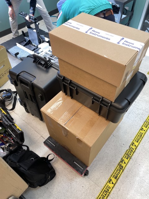
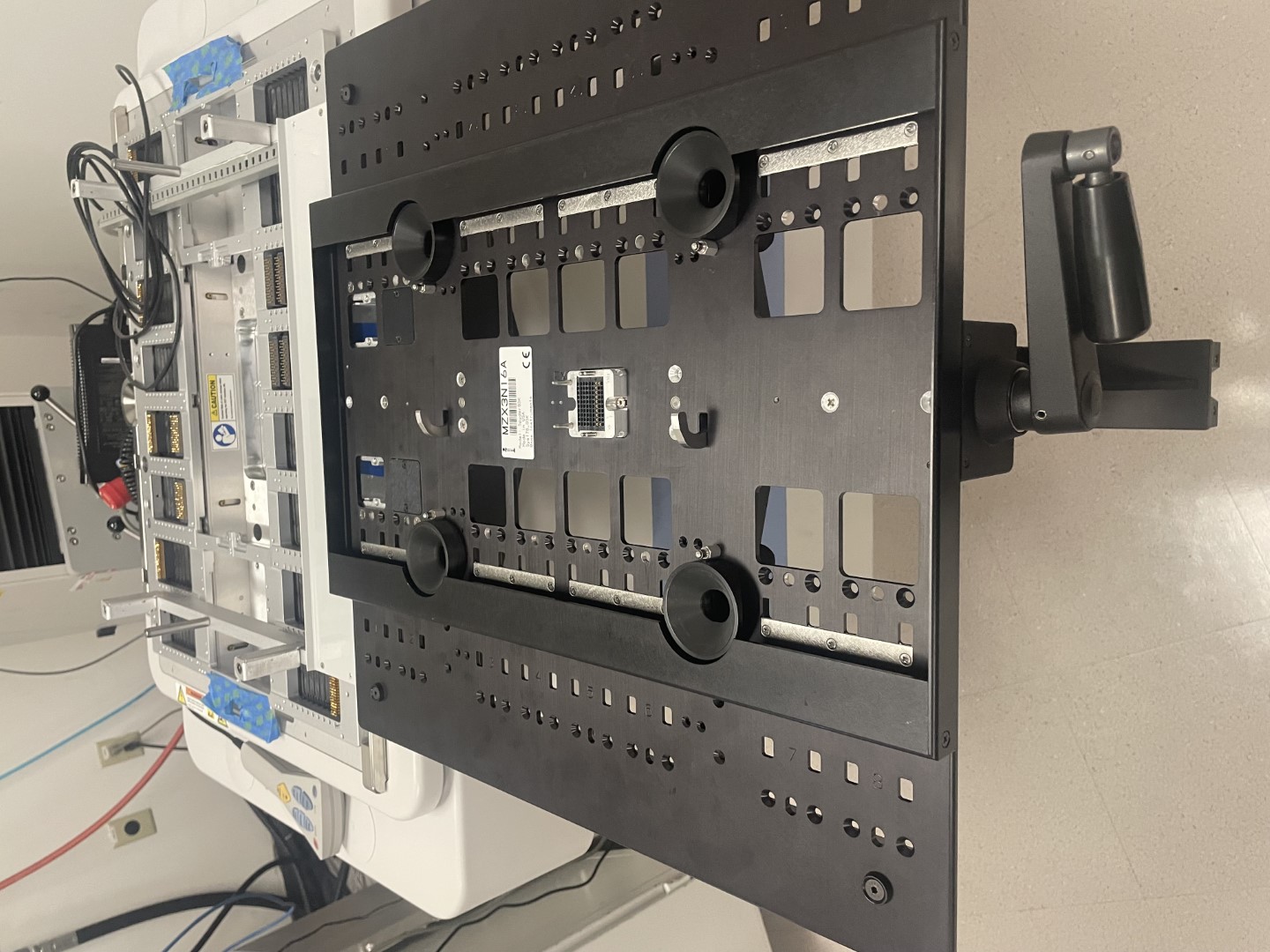
Figure 2: RI8611A Advantest V93000 Cassini Infrastructure Assembly
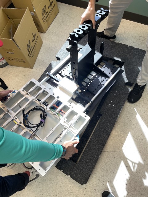
Figure 3: Location of the V93000 Floating Base Ring
Figure 4a: Locking the V93000 Floating Base Ring (Red X is Unlocked, Green check is locked)
Figure 4b: Locking the V93000 Floating Base Ring Photo
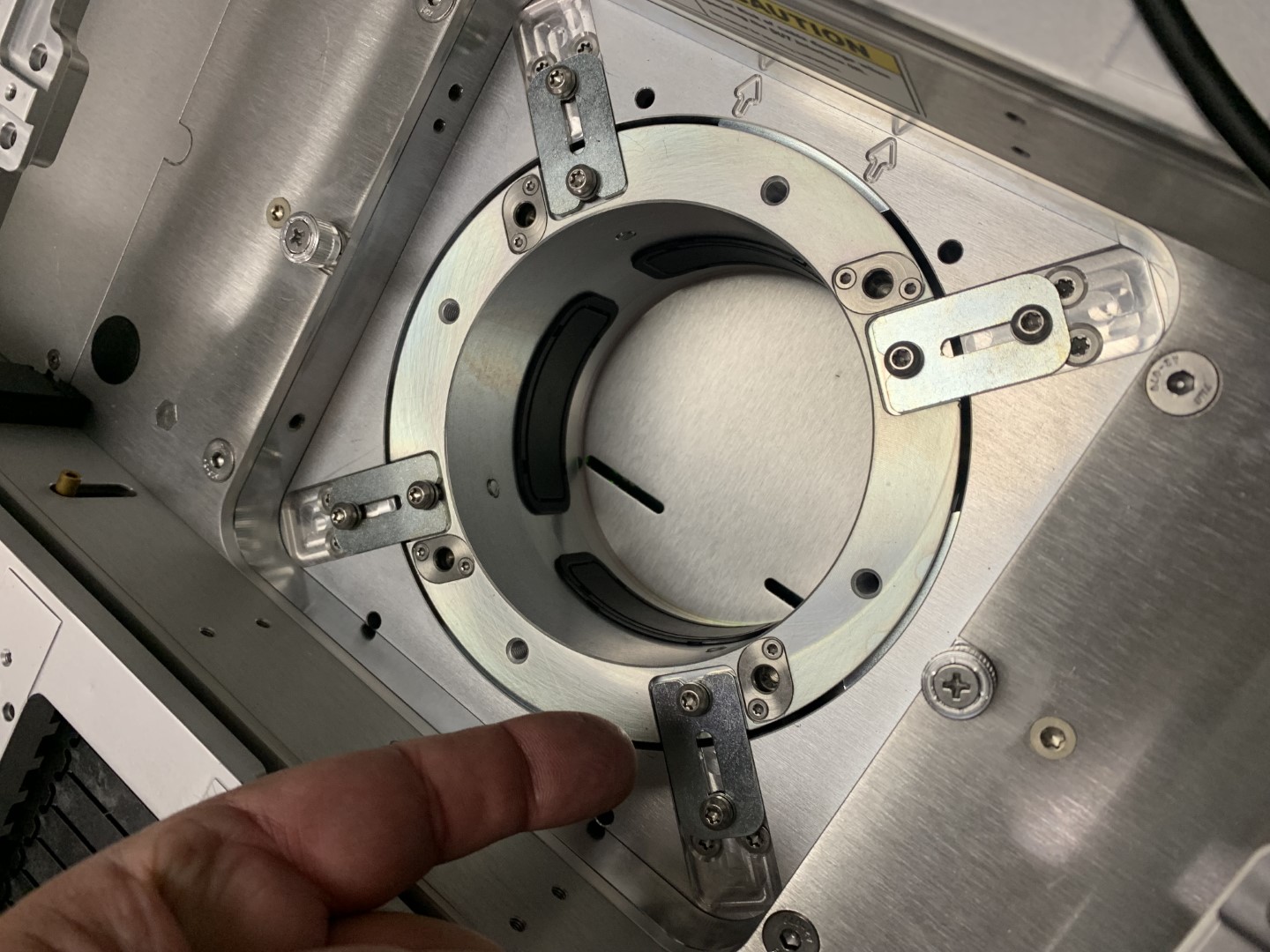
Figure 5a: Align and Attach Infrastructure
Figure 5b: Attach the Infrastructure Cover
Figure 6a: Bumper and Power Supply
Figure 6a: Bumper
Figure 6b: Power Supply mounted to head
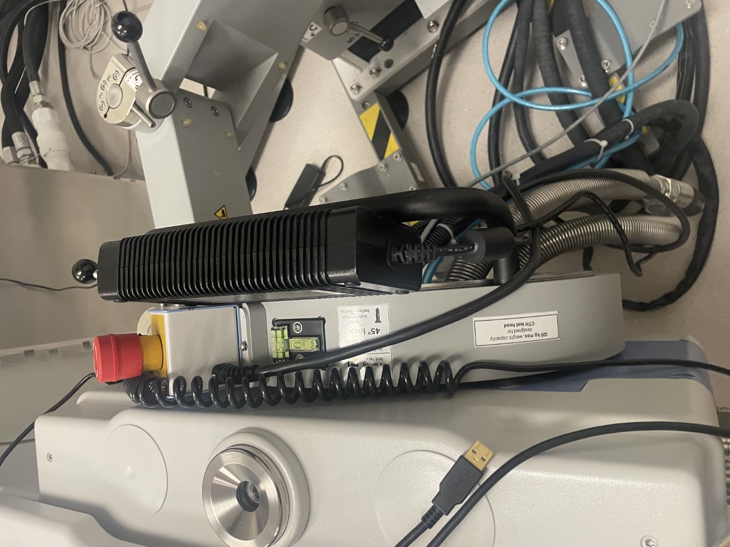
Figure 6c: Power Supply mounted to head, and USB Command and Control cable alternate angle
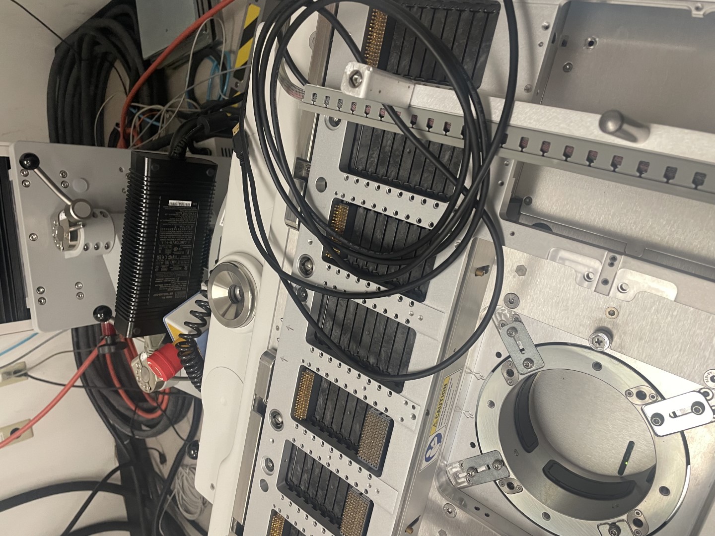
Figure 7: DC Power Plug for 48V Power Supply
Figure 8: Alignment Adjustments
Figure 9: To Adjust Advantest V93000 Manipulator Arm
Figure 10: Infrastructure attached to Advantest V93000