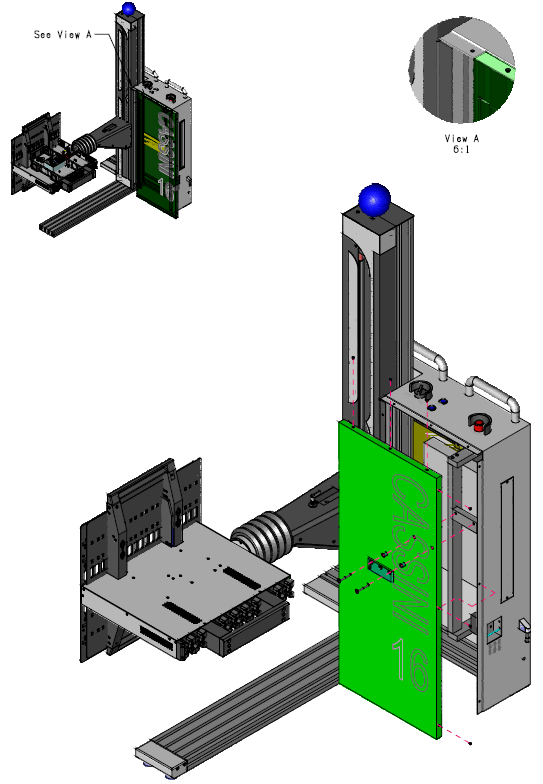
The Cassini 16 Infrastructure provides 3 service panels to access the conditioned power supply modules, RIFL hub (communication and shared 10 MHz clock), Front and Rear RIFL Top boards, pneumatic Fixture locking and mechanical foundation for the System Controller (EPC) and all 16 Cassini TIMS in the Test Head. Contact Support ([email protected]) for specific instructions for diagnosing or replacing malfunctioning items.
Tools Needed:
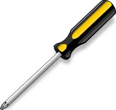
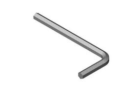
#1 Philips (All Panels) -AND/OR- M4 Allen Wrench (Mainframe Service Panel). Replace power supply with #2/3 Philips.

There are NO electrical shock hazards from any of the exposed electrical connections on the test head or on any surface of the system. The system uses 48 volts or less and shock hazards are typically designated as to 50 volts or higher3. No high-voltage cables or connections are exposed at any time during operations or when moving the system. Fixtures and Tester Instrument Modules (TIMs) can be safely removed "hot" without disconnecting power without damaging the equipment or exposing live connections to the operator. The system is equipped with an Emergency Off (EMO) button that instantly disables all 48 volt connections.
The "Main Breaker" is used to disconnect all electrical connections and should be switched "Off" before performing any infrastructure maintenance that requires tools to remove protective metal covers. The side breakers labeled "TIM Front", "TIM Rear", "Head" or "Mainframe" can be switched "Off" before opening specific service panels.
Test Head Service Panel
IMPORTANT Switch the "TIM Front" & "TIM Rear" (RevA) or "Head" (RevB) side breakers to OFF before opening the Test Head service panel.
The Test Head service panel can be opened to access the RIFL board, Test Head fans, control board, power distribution and other components in the Test Head.
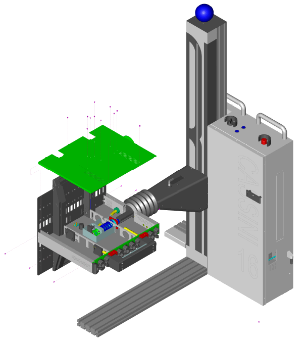
The diagram below shows the 16 screw locations needed to remove the access panels for either the Test Head or Front panel, 3 on the back, 12 on the top, and 3 on the front. Remove ALL TIMs and rotate the top of the Test Head away (as pictured).
Power Supply Module Service Panel
IMPORTANT Switch the "Main Breaker" to OFF before opening the Power Supply Module service panel.
The hot-swappable two redundant 48V 800W 16.7A power supplies (RI PN GR1PWF2A) can be independently replaced if either AC Good or DC Good green lights are OFF. Before swapping, remove the single retaining screw with a #3 Philips Screw.
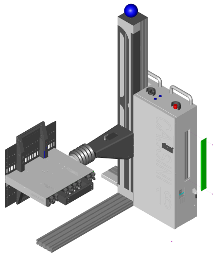
Mainframe Service Panel
IMPORTANT Switch the "Main" side breaker to OFF position before opening the Mainframe service panel.
Unscrew the 6 Philips head screws and 2 Allen head screws and AUX mount plate from the front of the panel. Slide the panel away from the tower by pressing firmly on the front and pushing outward as seen in View A and the zoomed View A diagrams.
