

RI ATE System Controller
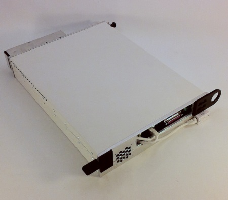
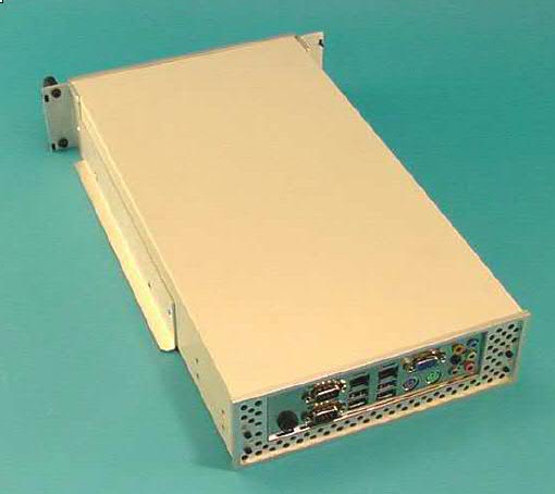
Instead of utilizing a non-deterministic distributed processor approach, the RI Cassini ATE system uses a single, high performance system controller and a proprietary high speed third generation communication interface called RIFL III (Roos Instruments Fiber Link Three) to control critical test sequence timing and ensure total execution time repeatability. The original implementation of RIFL utilized a token ring fiber optic bus ( hence the name RI Fiber Link ), but in this third generation it is implemented using a high speed star Lan configuration while still utilizing the original serial RIFL protocol language for even higher throughput now with Plug and Play capability. This architecture takes full advantage of the rapid technology growth in the consumer computer market, allowing for relatively low cost system controller performance upgrades and ensuring a long product life cycle. The Cassini System Controller is an embedded computer that can be easily replaced in the field. Either the replacement system controller will come pre-configured with the correct Guru ID from the factory or a USB Guru Security dongle can be easily swapped from the old controller to the new controller and the system will rebuild the entire environment from a Guru backup server.
System Controller
Functions:
User Interface
System Management
Test Plan Generation & Execution
Measurement Control and Signal Processing
Data Analysis
Contents:
x86 (Intel/AMD) embedded computer
ArcaOS Operating System
RI System Software and Guru
System RIFL III Interface
The RI Fiber Link (RIFL) found in early RI7100A systems used optical cables, but RIFL II uses shielded RJ45 cables (not typical "CAT5" network cables) while RIFL III, introduced with Cassini, uses a distinctive 10-pin round connector.
The RIFL ports are not ordered, so any device can be attached to any available port on the RIFL hub. To connect a RIFL cable, RIFL III (Round 10 pin) connector into an open RIFL port, until it clicks. To remove, press down on the tab along the top of the connector and pull. You can plug the cable into either the hub or the instrument first, the order does not matter. RIFL II to RIFL III cables are sometimes used to connect the different physical interfaces.
RI System Control Interface with RIFL III
RI Cassini ATE System Communication and Control
RIFL III and RIFL III to RIFL II connectors
RI Instrument Control thru RIFL III Decoder Module
External GPIB control through RIFL II to GPIB Interface Pod
Plug and Play auto configuration of RIFL Nodes
Scheduled Timing and Event Control with 1 μsec resolution
The RI System interface and the RIFL III network bus provide the test system's internal low latency communication and instrumentation control link. The System Controller provides a RIFL III interface connection and 10 Mhz timing clock signal used throughout the system similar to a typical computer network or usb hub configuration. Each RI instrument contains a RIFL III interface connection and a RIFL III Decoder Module. RI instrumentation in the test system do not contain microprocessors for control. Control of all functions is provided by the System Computer through the RIFL III bus to the RIFL III Decoder in each RI instrument. A RIFL Decoder Module is an independent node on the RIFL network bus.
To control any GPIB instruments in the system, an RI System GPIB Pod is required to make the instrument appear to be another RIFL node. The GPIB Pod contains a RIFL III Decoder Module, a RIFL III to GPIB Interface board and GPIB connector for connecting GPIB cables between the RI System and any GPIB instruments.
The RIFL bus is a self addressing (plug and play) interface. The RIFL interface transfers serial data, and provides the system with 1 μsec scheduled timing and event control. The RIFL II RJ45 interface was replaced by a distinctive RIFL III 10-pin round connector that is electrically identical to the RIFL II connectors.
NOTE: RIFL II will NOT operate using unshielded Category 5 (CAT5) cable typically used on computer network LANs.