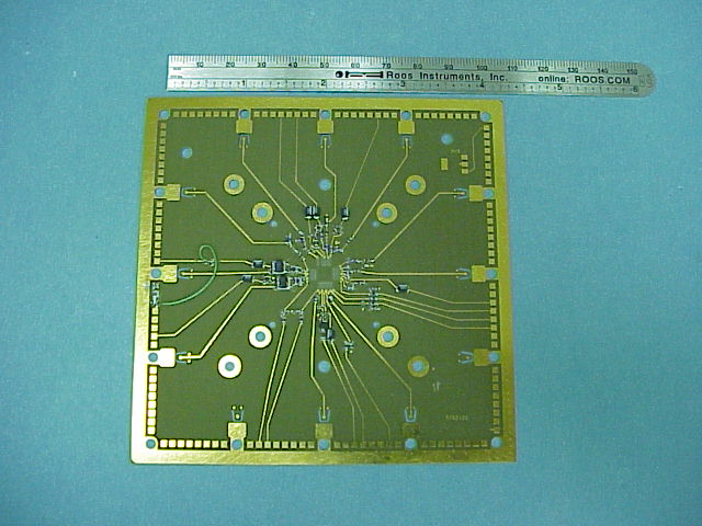
Here is a typical dut board from the bottom side. The dut and socket are on the other side. You see outside DC pogos and thre 12 RF launches. In this case 10 of them are used. The traces are dimensioned, considering the dielectric for 50 ohms. The vias (to get to the socket side) are dimensioned appropriately as well. Note the close physical proximity of decoupling to the actual part.
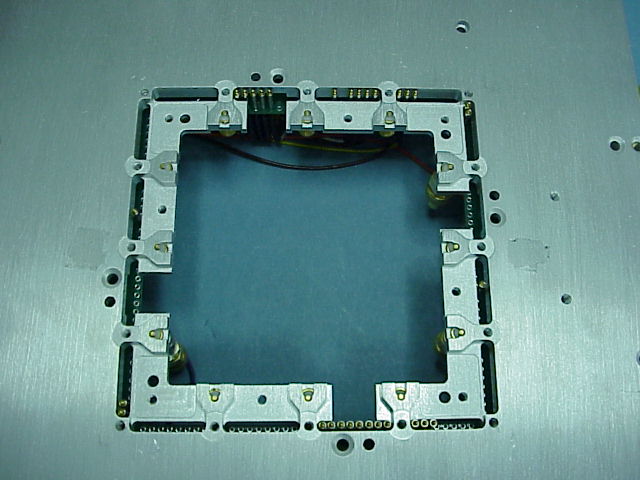
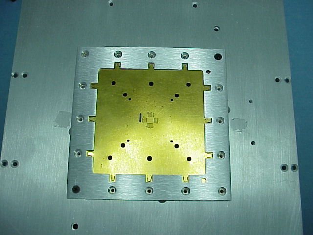
Here is the view of the fixture top plate. You can see the DC pogos coming from the inside and the 12 RF SMA sparkplug launches.
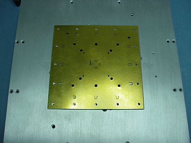
The Dut board is inverted then placed on the fixture top plate. There are two alignment pins/holes to insure proper orientation. (They are not populated in this case)
Now the dutoard clamp is put in place.
Here is how the socket attatches.
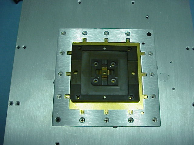
This is the view of the underside of the topplate, This is what is inside the picture.
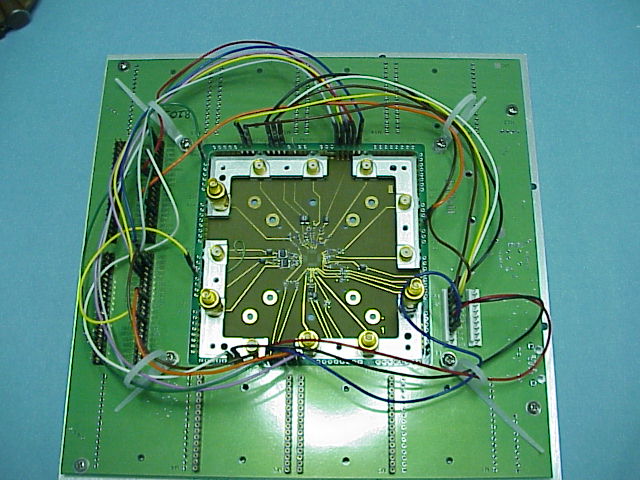
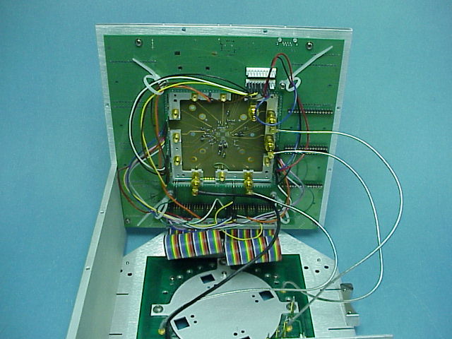
Here the topplate is attatched to a fixture bottomplate in debug mode. The coaxial connections from the tester pogo ring to the dutboard and launces are shown.