![]() See Also DUT Interface Board (DIB) Design Guide for more overall design information and examples.
See Also DUT Interface Board (DIB) Design Guide for more overall design information and examples.
DIB Layout for the Matrix Top Plate
There are five types of interfaces to the DIB in regard to the Matrix fixture.
- DC
- Digital
- RF - MCX dual - 6GHz
- RF - SMA single DC - 10 GHz
- MM wave DC - 40GHz
1. DC Interface:
The DC interface is basically comprised of a Delrin block with pogo connectors pressed into it. It is a 4X4 matrix with 0.100 pin centers.
DIB Pogo Landing | DC 16 Block | Jumper Install DC 16 Block |
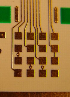 | 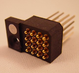 | 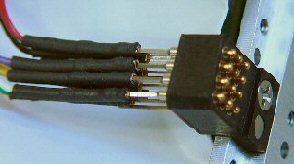 |
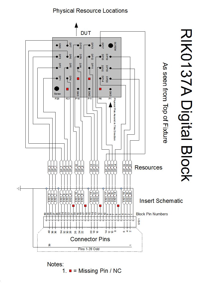
2. Digital Interface:
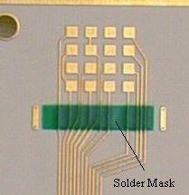
The fixture digital interface incorporates a controlled impedance for each of its contact pogo pins. The block is a 5X6 Matrix with the pogo pins soldered to a PCB back plane.
NOTE: Digital blocks can not be placed side by side due to connector!!!
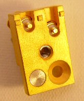
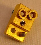
Digital Pogos | Digital Cable Side | Digital with Cable |
 | 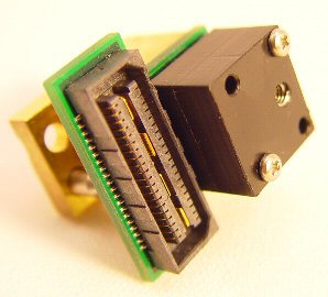 |  |
Digital landing 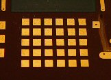 | ||
(See Block Pin Out Below) |
 |
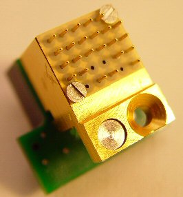
3. RF Dual MCX - 6GHz:
DO NOT USE FOR NEW DESIGNS, Use RIK0117A instead.
This interface is composed of a single block with two MCX panel mount connectors side by side. It is intended to be for RF connections with a bandwidth up to 6Ghz. The DIB interface has a cutout "tongue" that makes contact with the connector center conductor.
NOTE: 50 Ohm trace is intentionally placed at edge of launch center conductor nearest DUT to prevent parasitic stub effects at frequency.
MCX Interface | MCX Cable Side | MCX Landing |
 |  (MCX straight cable only) | 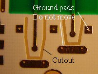 |
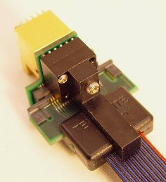
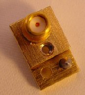
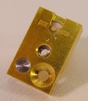
4. RF Single SMA - 10GHz: RIK0117A
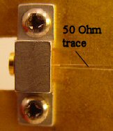
The SMA interface block is a mechanical assembly composed of a single press-in connector and brass mounting. The DIB interface has a cutout "tongue" that makes contact with the connector center conductor. Placement of the grounding pads and their related ground vias is critical. They have been optimized for best performance and their locations should not be adjusted from the gerber template locations.
NOTE: 50 Ohm trace is intentionally placed at edge of launch center conductor nearest DUT to prevent parasitic stub effects at frequency.
SMA Cable Side | SMA Interface Side | SMA Landing |
 | 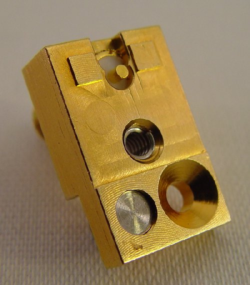 | 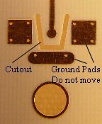 |
5. RF Single SMA - 15GHz: RIK0212A
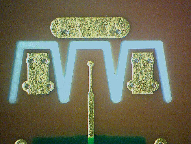
Consists of a single press in SMA adapter. It is designed for use on the Matrix top plate and is placeable at 0.5" pitch. It is intended to be for RF connections with a bandwidth up to 15 Ghz. The DIB interface has a cutout "tongue" that makes contact with the connector center conductor. Each of the ground pads have their own "tab" for connection.
NOTE: 50 Ohm trace is intentionally placed at edge of launch center conductor nearest DUT to prevent parasitic stub affects at frequency.
15GHz SMA Cable Side | 15GHz SMA Interface Side | 15GHz SMA Landing |
 |  |  |
 SMA 3 launch dim DIB expanded.pdf
 SMA 3 launch dim DIB.pdfPDF mechanical drawing with dimensions
6. RF Single MMPX - 40GHz: ( RIK0156A )
MMPX 20/40GHz Cutout (Board Bottom to 20Ghz) | MMPX 40GHz Installed (Board Top to 40GHz) | MMPX Extraction Tool RIK0257A |
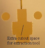 |  Trace is coplanar | 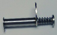 |
92_MMPX-S50-0-1 PCB Layout | Questionnaire for PCB Layout Simulations to Huber+Suhner |

Clamp Drawings:
Top Plate Assembly:
The fixture top plate assembly includes the top plate, pedestal support, pedestal, DIB, and DIB clamp.
Pedestal & Support
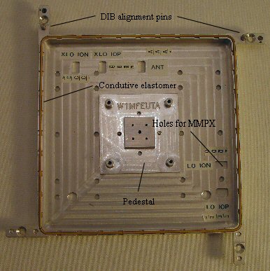
Support / Pedestal / Dib / Clamp Sandwich
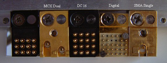
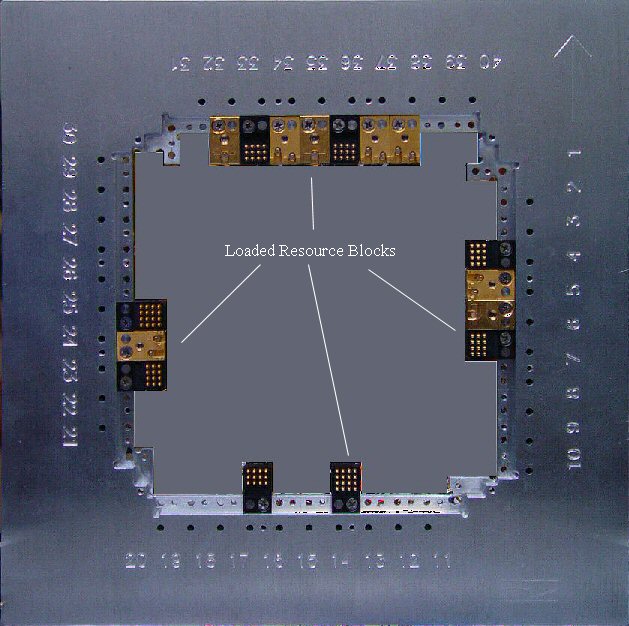
Installed Blocks on 0.50" Pitch
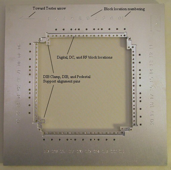
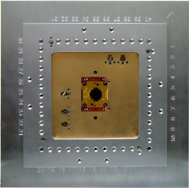
Matrix Top Plate
DIB Bottom Side
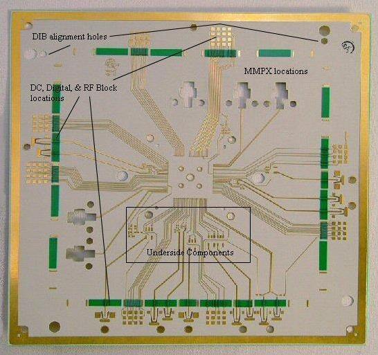
Notes: Consider using double layer solder mask over DC lines to prevent shorting to pedestal support.
Support / Pedestal / Dib / Clamp Sandwich
Installed Blocks on 0.50" Pitch
Matrix Top Plate
DIB Bottom Side
Notes: Consider using double layer solder mask over DC lines to prevent shorting to pedestal support.
Top Plate With Blocks
Matrix Top with Pedestal and Support
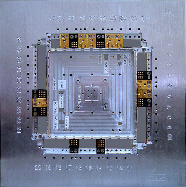
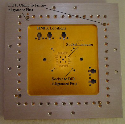
Matrix Top with DIB and Socket
Matrix Top with Pedestal and Support
Matrix Top with DIB and Socket
Example Gerber and DXF and Drill Files: (Accessible online @ http://roos.com/docs/DFES-8D3W59?open )
 Y000CCA0.zip
 Y000CCa0.pdfGerbers
Finish Callout for FR-4 or Rogers: