

This Applications note addresses making measurements on devices under pulsed conditions and describes several methods for realizing Pulse Stimulus signals and Pulse Measurements specifically using an RI8546 Device Power Supply TIM, an RI8508C Digitally Modulated RF Source TIM with an RI8567B Integrated Test Set/Receiver TIM.
Since all the RI ATE Systems are synchronous, triggered, integrated systems that allow timing control over all the tester functions to a resolution of 1uSec, realization of pulsed testing is just a manipulation of the standard products measurements to fit the timing required. This timing control is accomplished using the Pre and Post measure group functions, where the application developer can control the timing of the DC supplies, DC measurements, RF sources, and RF measurements to implement a Pulsed measurement methodology especially useful with high power devices that have significant heating effects over time.
Our modern mobile radio based communication systems utilize time segmented multiplexing schemes, with a short pulse and long duty cycle. An RI ATE System is typically called upon to produce a Voltage and/or RF Signal for a specific duration and repetition rate, while measuring Current and RF power before, during and after the pulse. DC current pulse profiling as well as pulse power averaged over a number of cycles are also typical measurement types.
The examples test panels provided here focus on the specific buttons that control the RI8508C 6 GHz RF Source and the RI8567B Test Set / Receiver since this is the most popular setup for most RF Communication Device testing. These techniques may be applied to other TIM's as well, so please contact RI for assistance with other configurations.
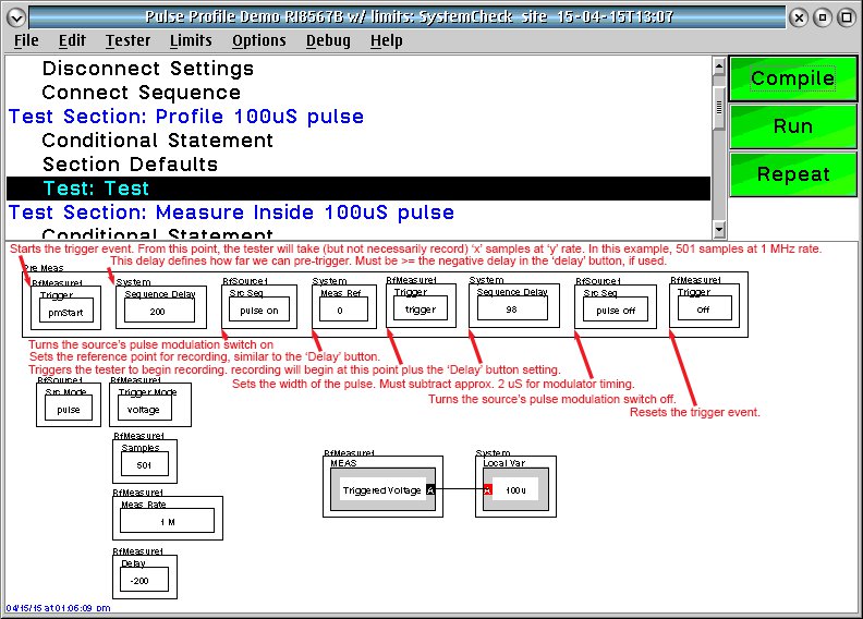
Since we will be pulsing signals at specific timing we need to first set up and define the initial states before the pulse operation begins. Several buttons are shown to provide static initial condition setups and then using a Premeasure Sequence, we will control all the parameters of the pulse signal which is described in order of execution in table 1.
The First Example Test Panel demonstrates profiling of the Rf pulse as the reference test for the table 1 descriptions.
Order | Action | Process |
1) | Sets the RF Measure1 Trigger button to "pmStart" which defines this as the start in time of the pulse measurement operation (samples are taken at the rate in time defined by the "Meas Rate") but not yet recorded as the number of "Samples" set in the panel. This allows pretrigger data collection. | Be sure to place an RFMeasure1 'Trigger Mode' button in the Test plan to define the type of measurement to be triggered here in this example we are setup to measure "Voltage" |
2) | Wait the amount of time designated by the System Sequence Delay button (this case 200 usec ) NOTE: This must greater than or equal to the amount of pretrigger delay associated with the measurement set by the "delay" button and owned by the measurement instrument. | Place the number of usec in an RFMeausure1 "Delay" button to tell the compiler first how much pretrigger is available for this instrument. This number should be negative since it depicts a pretrigger time. |
3) | Enable the RfSource1 "Src Seq" button to set "pulse on" and trigger the pulse event in time. | Place an 'RfSource1 "Src Mode" button set to "Pulse" to define the initial condition (and ending condition) of "rf power off" for the source power. |
4) | Set the system wide reference point in usec for the measurement sample recording by using the System "Meas Ref" button. Here we set it to the typical time = "0" | Useful if more than one instrument is involved in the pulse sync then this will align all the start times and allow an group time reference shift if needed to align with external events. |
5) | Trigger the RfMeasure1 instrument to start recording the number of "Samples" set at this time plus the "Delay" set for this instrument in the panel (here we had set a -200usec) | Be sure to place RfMeasure1 "Samples" and a "Meas Rate" buttons in the panel to set the number of samples at the desired rate in time to be recorded strating at the trigger event. Here we used 501 samples @ a 1MHz rate |
6) | Set the duration (width) of the pulse in usec using the System "Sequence Delay" here. NOTE: there is a small amount of overhead (approx 2usec ) so adjust the delay accordingly. | Since we are attempting to set a 100 usec pulse width rf pulse, we set the "Sequence Delay" to 100 -2 ( for the overhead ) = 98 usec. |
7) | Turn the RF signal off to end the pulse by setting the RFSource1 "Src Seq" button to "pulse off" | Remember the 'RfSource1 "Src Mode" button set to "Pulse" defines the ending condition of "rf power off" for the source power. |
8) | Terminate the Trigger mode event and reset the event engine for the instrument by setting RFMeasure1 "Trigger" button to "Off". | A Postmeasure group may also be added if necessary to return any other instruments or DUT states modified in the Premeasure to a know state before exiting the panel. NOTE : Remember the State table is not updated when states are modified in a Premeasure group, and will only be changed if a subsequent panel modifies the state from the value previous held in the state table. |
9) | In the panel define the measurement of RfMeasure1 as one of the available triggered types for the measurement to utilize the trigger information in the Premeasure group. Here we set the Meas type to "Triggered Voltage" to get a complex Voltage vector (Mag & Phase) for each. | Place the data collected into a local variable ( Array Variable if multiple states are varied in the panel ) and extract the data in a calculation panel later to allow for data manipulation before saving into the database. |
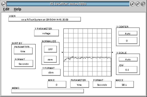
First Example: This panel profiles the data taken from a 100usec RF pulse. If in the global or section defaults the b2 measurement parameter is set then this will profile the output of the device, if it is set to a1 then the data will be for the Rf signal supplied to the device.
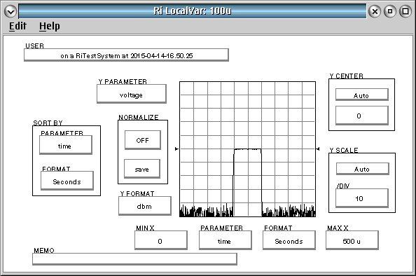
Looking at the local var save from this test panel clearly shows the 500 uSec of captured data in 1 usec increments and where the 100uSec of RF pulse signal occurs vs the samples in time. In the panel we set the pretrigger delay to 200 uSec so the first 200 samples are from before we turned on the Rf pulse, then the 100 usec of RF signal followed by the rest of the samples until the 501 sample are recorded...here that was an extra 200 samples past the end of the Rf Pulse.
The resulting 100 uSec pulse rise time is about 4 uSec so you see that the rising edge is represented by only a few samples. This is good for debugging purposes, but later we will show an example of modifications that would make a better production test once the design criteria are satisfied with this characterization type test.
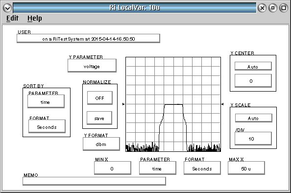
Taking the data again and modifying the test parameters to sample the same 501 points of a 10 uSec pulse prolife, the rise/fall times of about 4 uSec are easily seen.
In the next example we are measuring the 100 uSec pulse, but the settings are adjusted to just capture 101 samples at the top of the RF pulse. This is much more tailored for production testing once the pulse profile effort has been completed and verified.
This data is then manipulated in a calc panel to compress the data into a single data save for Limit checking and Device binning.
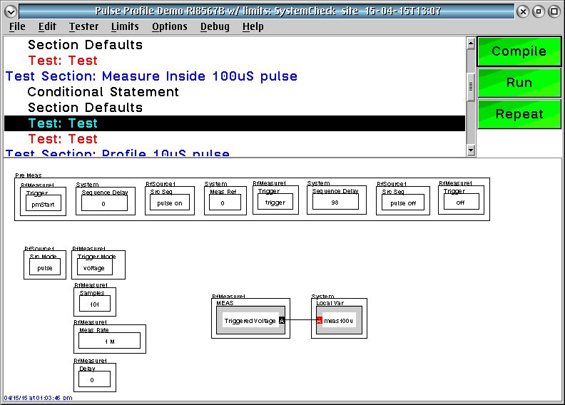
The resultant raw data of the RF signal during the duration of the pulse shows it takes some time to stabilize the power in the beginning of the pulse, and then drops off rapidly at the end.
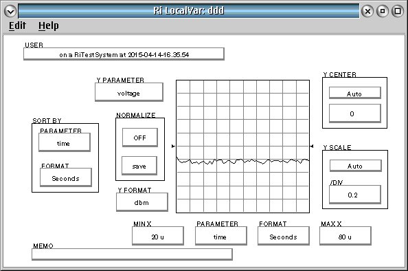
To have more consistent results in production we manipulate the data by throwing out the leading and trailing 20 uSec of data (about 40 points) and average the vector voltage data to remove random noise in the 60 points in the middle (from 20 to 80 uSec). The average power reading is more stable and consistent across devices, and now readily available to put in the database and limit check as a single value.
FYI.... Below are the result after removing the first and last 20 uS. Note the graph is from 20 to 80 uS:
NOTE : To Change the pulse width to a wider or narrower pulse, the three buttons to modify the values of are:
1) The second system "Sequence Delay" in the "Pre Measure" group....The example is using a 100 usec pulse width rf pulse, therefore the "Sequence Delay" is set to (100 -2) { the -2 usec is to compensate for the overhead } so in this case the value used is = 98 usec. To make a 50 usec pulse the value would be 48....to make a 500 usec pulse the value would be 498.
2) The "RfMeasure1" "Samples" sets the number of measurements recorded once the "Triggered Voltage" Measure is started. The example is using a 100 usec pulse width rf pulse, therefore the "RfMeasure1" "Samples" is set to 100 +1 more ( which is multiplied by the "RfMeasure1" "Meas Rate" button set here to a 1 MHz rate which is a 1 usec rate ) to cover all of the time the pulse is on. To make a 50 usec pulse the value would be 51....to make a 500 usec pulse the value would be 501.
3) The "RfMeasure1" "Delay" sets the time in usec from the trigger event that starts the saving of the data, until the number of samples set by the "RfMeasure1" "Samples" is filled by the "Triggered Voltage" Measurement. This would normally be set to 0 in a production implementation so that the samples recorded are the set that occur during the time the pulse is actually on. To profile the pulse or to see pre and post pulse data, adjust this delay and adjust the sample size to provide the data covering the events in time you want to analyze.
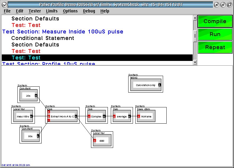
Sample test plan