

Since most RF / Microwave Integrated Circuits have multiple high frequency pins with some gain and/or isolation from other high frequency pins, most ATE applications utilize independent, 8 term, one port calibrations that are sufficient to measure S-Parameters accurately. This is because the S12 and S21 terms of the Device under test are typically not close to 1. For instance, in an amplifier, the output and input tend to be reasonably well isolated from each other. As such, mismatch effects at the input are a secondary effect at the output.
However for some classes of device, such as low loss switches or transistors, can have the test system attributes at the input and output at the device interacingt through the device and cause errors significant enough to be a first order issue.
Here is an example of an S21 measurement of a low loss RF MEMS switch.
In this case there is a residual ripple of as much as 0.3 dB, even with the input and output part both having an 8 term, 1-port cal.

For this case of device, a more accurate approach would be to implement the more traditional 12 term error model, with the addition of a thru measurement, which will be better at removing the ripple effects of the transmission tracking errors.
The process involves adding a new very specific cal data variable object to the collection, that represents the thru calibration terms.
In the Ri Fixture environment, fixture paths define connections from the test head all the way to the device.
For instance:
PortRf3DutRf3is a path that connects Testhead port RF3 to the Dut interface port DutRf3
PortRf6DutRf6 is a path that connects Testhead port RF6 to the Dut interface port DutRf6
In order to hold the transmission cal data (the thru), a cal data variable needs to be created between DutRf3 and DutRf6.
Following the convention it must be: DutRf3DutRf6. (The capitalization is critical)
To add this to a either Fixture or a Device-Interface file, use the Ri Device Connection Editor and add a path that has no connections ( "None" in the Tester Assets and "None" in the DIB board connection )
but has a Cal Variable name that is specific to the paths that will be calibrated...in this case RF3 and RF6
Now that the Calibration Variable path object has been created, a calibration Test Plan must be created. It takes the form of all the RiApps fixture calibration, containing the three elements of a cal:
1.) The "reset calibration" of the path
2.) The measurement of the data
3.) Writing the calibration data into the path.
There are several Ri Template Cal Test Plans available to use as starting examples for the customer to customize with their own paths and variable names.
Since this cal is looking for the maximum accuracy available, the measurement of S-Parameters is suggested.
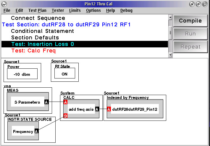
This panel includes the reset cal and the write cal.

Note the special Calc: as2PorTThrutEA.
That is a text block cal that uses the text in the attached txt file.
the text is: [ :a | a as2portThruEA ]
This uses a special method in the Ri Software to take the S-Parameter measurements of the thru and create the cal values that contain the transmission tracking information.