

I2C is a common serial protocol that is supported natively by the RI ATE StaticDigital Instrument as well as the DPins instrument in the Universal Digital TIM. I2C differs from SPI buses in that it is a 2 wire bus, clock and data.
This document is not meant to be a tutorial ion I2C, that is left to other sources, it will however, describe how to implement it on the RI ATE Platforms.
The I2C protocol is 24 bits long divided into three 8 -bit words. The first 8 bits are the I2C address, typically the address of the specific chip on the bus. The second 8-bits are the register address inside the chip and the last 8-bits are the data payload.
RI software treats I2C as a special case of a serial type bus. For more information, please review these documents Serial Bus Control; Defining the DUT, Serial Bus Control; Testplan and Serial Bus Control; Data Read.
Hardware:
Since I2C is a two wire bus, therefore read and write share the same pin.
For clock speeds above 1 MHz, use the DPins instrument with the clock assigned to either Pin 5,10,15 or 20 and any other pin for the serial Read/Write.
If the clock speeds required are less than 250kHz, then any pin in the Static Digital instrument resource may be used.
When a faster clock speed is required, the StaticDigital instrument has two sets of dedicated higher-speed pins that support up to 1 MHz:
Read: DB1 or DB9
Write(Data): DB2 or DB10
Clock: DB3 or DB11
So in applying the Static Digital tester resources, two DB lines (R and W) must be tied together. For I2C as well as other fast serials DB1 and 2 or DB9 and 10 are the recommended pins to use .
We suggest physically tying them together at the DUT, and then connecting to the serial bus Hi voltage supply through a 5K pull up resistor.
Since the StaticDigital instrument does not have a bidirectional R/W mode, this can be emulated by connecting a series resistor from the designated DB write pin resource to the designated DB read pin, and then connecting the read pin to the DUT's R/W pin.
Then use DB 3 or DB 11 respectfully as the clock line.
The DPins instrument, however, does support bi-directional communication over any available pin. For example, connect DPins1-1 for data use DPins1-5 as the clock.
DPins Locally Defined Control:
Read the Cassini Reference Guide, CH 2 Graphical Programming | Section 4 - RI8535: Universal Digital, Edit Panels

Specifically the Serial Data button with the "i2c" protocol. Text string input button that generates a serial emit pattern for the serial data output. Data is input as protocol:packet size:write data:
read mask.
I2C protocol emit with 8 data clock edges and 1 ACK bit that is emitting the hexadecimal byte CF (1100 1111) and ignoring any read bits.
Example:
Static Digital Locally Defined Control:
I2C Protocol Example Test Panel -
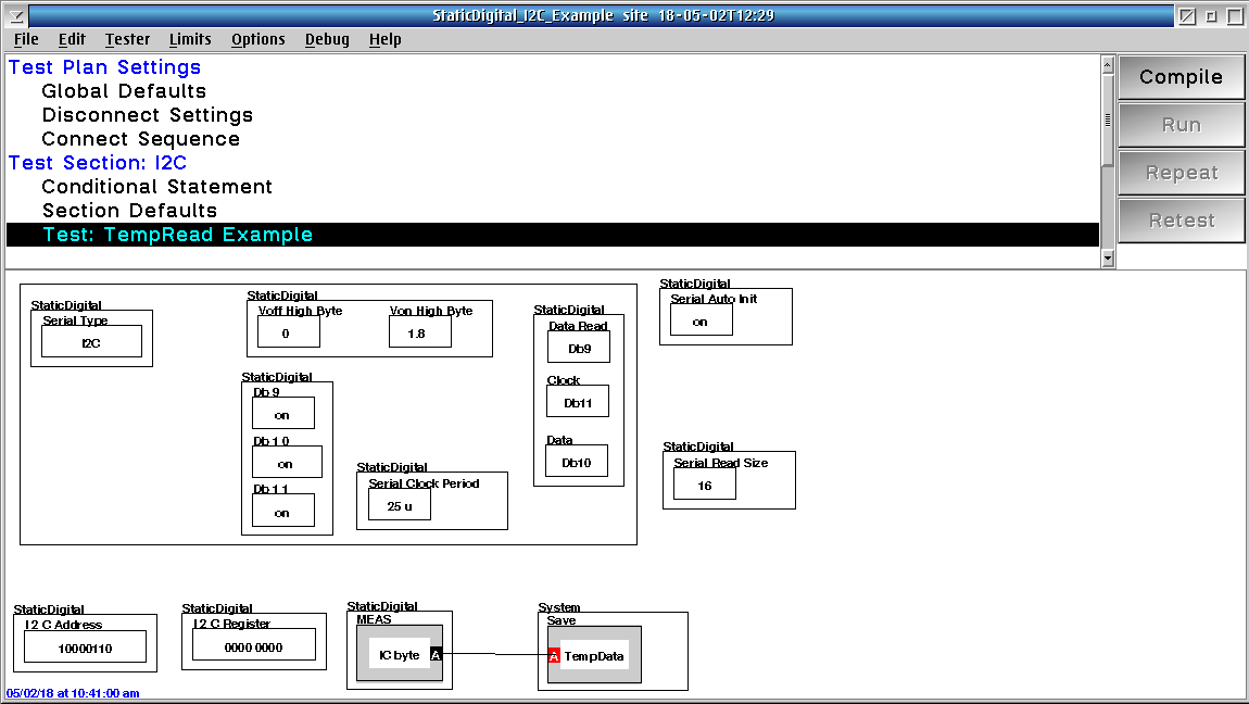
The Db9, Db10, Db11 buttons define the voltage state of the read, write, and clock pin when not in use during the I2C protocol (all set to ON, 1.8V)
The Serial Clock Period button defines the clock rate (40kHz in this case)
The Von High Byte and Voff High Byte buttons define the voltage logic (1.8V) for the DB9-DB16 pin resources used.
The Serial Read Size button defines the number of read clocks generated for the IC byte measurement block.
the IC byte measurement block captures the data. Note that the software will automatically toggle the R/W bit in the I2C protocol when there is a measurement block in the panel.
The I2C Address button defines the I2C slave address, the I2C Register button defines the I2C slave register, and the I2C Data button (not shown in example test panel above) defines the I2C data written to the register.
The Serial Read Size defines how many read clocks, i.e - a value of 16 means two 8 bit (byte) reads with an ACK in between.
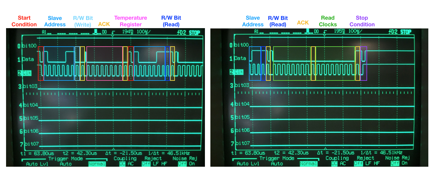
We can monitor the I2C signals with a Digital Scope or Logic analyzer as shown below:
Protocol Aware Interface: Dut Definition
The StaticDigital Instrument and the High Speed Digital TIM all will use the protocol aware definitions if they have been created and are available on the system.
RI7100A
1.) The DUT is where the Serial type is defined. We picked I2CFormat as the Style
2.) Start the Dut definition with the I2C register address, ignoring the I2C part address. The part address will be dealt with later.
Therefore it will look like a 16 bit word with the first 8 bits being the I2C register address.
Cassini
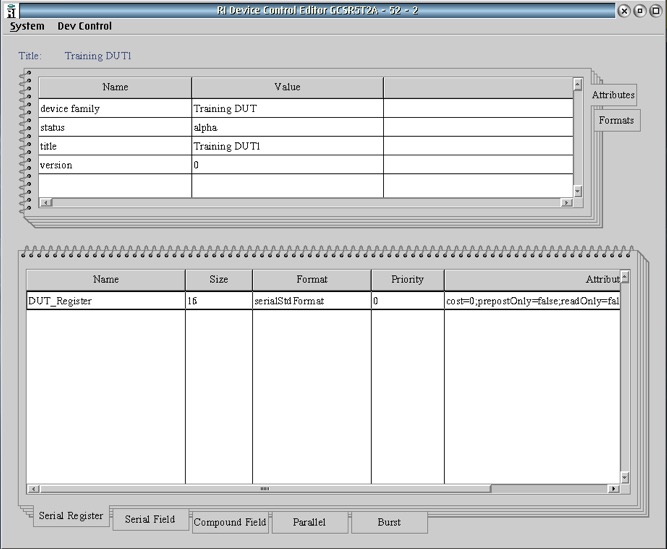
1.) For the RI Cassini System, there is an application called Device Control Editor that handles all the tasks required to support a protocol Aware interface.
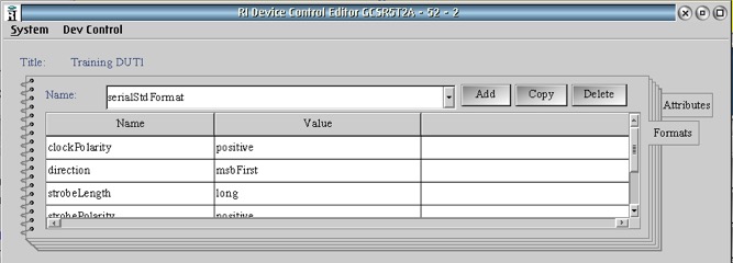
The second tab on the right side of the top window is the Formats tab and where the Serial type is defined. We picked I2CFormat as the Style
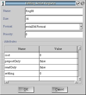
2.) Start the Dut definition with the I2C register address, ignoring the I2C part address. The part address will be dealt with later. Therefore it will look like a 16 bit word with the first 8 bits being the I2C register address.
Global Defaults
The main differences between I2C and other serial implementations are shown below:
1.) The Serial Type is DUT Defined. (In the dut it is the defined as I2C)
2.) Use the I2C address button to define the part address of the DUT. And make it seven bits as the 8th bit is reserved for the tester as R/W
3.) Define the StaticDigital Von, Voff, Data Read, Data, Clock, Serial Clock Period as you would with other Serial Types
4.) DB2 is set as "open Collector" This is what allows the tester and part to communicate with the "Ack"
Data Write:
This is exactly like all other dut defined Serial
Data Read:
1.) This is slightly different as the I2C Register that is desired must be specified.
Data Write and then Read
A write and read can be combined in one panel
Here are the example panels and dut file