

It a TIM reports DISABLED slot when performing a system startup, the RIFL hub may be damaged and it could result in a TIM fuse needing to be replaced. Standard support procedures require that the TIM be shipped back to RI for repair. Contact [email protected] for RMA and safe shipping instructions.
Under certain rare conditions, it may be appropriate for the TIM to be opened and serviced on-site. All TIMs share the same case that can be opened for service and placed in use for diagnostics (attached to the Test Head) with the cover removed. DO NOT TOUCH any active electronics with the case removed without direct instruction from RI. TIMs can be safely removed from the Test Head with the power on. The software should be in an idle state; TestExec not running, no testplans compiled and the Fixture should be removed prior to removing any TIMs.
IMPORTANT: The Fuse is soldered to the bottom of the Y00070X# board and so the bottom cover should be removed. The top cover can be left in place.
Required Equipment:
GF1SZ12A, Fuse 5A smt 1206 (markings: white with grey 5 on back, green on front)
Soldering Iron, Flux, Solder, Solder Cleaner
#2 Philips Screwdriver
To open/close the case:
Remove the bottom half of the Cassini TIM. When placed on a table, The RI model/serial number label should be facing down. When loaded on the left side of Test Head, the TIM port on the upper right side, the side to remove is facing AWAY from you.
 On the bottom latch, unscrew the 2 left screws 10-15 turns but do not remove the screws completely. There are 4 total, do not loosen or remove the inner pair of screws.
 Unscrew the outer 2 right screws 10-15 turns but do not remove the screws completely. There are 4 total, do not loosen or remove the inner pair of screws.
- Orient the TIM so the text on the TIM label is upside down. Unscrew the 8 side screws on both sides. (16 total)
NOTE: Picture shows the TOP being removed, DO NOT REMOVE THE TOP!
- Pull the bottom latch until the cover clears the EMI/RFI groove of end cover. Pull the cover up and away from the TIM. Note that some TIMs have EMI/RFI elastomer gasket in the groove. Use caution to ensure the elastomer does not come out.
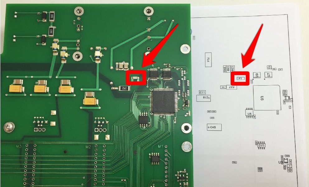
- Identify the F1 location on the board and remove the damaged Fuse. Solder the green side facing up.
NOTE: Picture shows the fuze installed upside down.
- After replacing fuse, replace the cover and tighten all screws. Verify functionality by latching TIM to Cassini Testhead and perform a System > Check. Run TIM specific diagnostics.