Purpose: To describe the creation of a fixture DC Voltage calibration factor to be used in subsequent test plans. This document will both describe how to generate this cal factor and how to recover it for subsequent testing. The idea is to use the Cal Data Save button to store a measured voltage value and then to use the CAL Factor Source button to recover it in a subsequent test plan.
Creation of the Cal Factor name:
- Activate the fixture that is to store the specific calibration data.
- With a right mouse button click (RMBC). pull down the fixture menu and request to inspect the fixture calibration. The Cal table inspection window for the fixture will pop up.
- Choose "Calibration entry" and then "Add Item". You will be prompted to type in a "new cal entry name".
- Type in the name and then press "OK".
- Go back to the fixture icon and from the pull down menu select "Save Calibration". The name of the cal data is now stored in the fixture calibration table.
- Deactivate and reactivate the fixture. Repeat steps one and two to make sure the offset name was really saved.
Creation of the Cal Factor name (alternative approach):
- Activate the fixture that is to store the specific calibration data.
- With a right mouse button click (RMBC). pull down the fixture menu and request to edit the fixture. A fixture definition window will appear.
- Select ADD on the right side of the Fixture Definition window and a Path Definition window will open (Figs.1&2). It is here that you will define the name of the calibration factor to hold the stored data.
- Begin the path definition for the pin by selecting the DUT Interface Pin field. To view the default choices for this field, click on the arrows next to this field using a left mouse button click. DutP1 was used for this example.
- Once the DUT Interface Pin has been defined, select the Test Head Pin field and choose the desired Test Head connection from the default list. V Meas 1 was used here. Also choose the Calibration Type required for this path. Calibration type None should be chosen even though we are going to store data into it.
Storing the calibration Data:
- The measured calibration data can be stored into the cal factor through a number of steps. It is first measured, changed to type "Voltage", and then stored into the Array LV called "arrayX". In figure 3 the data is generated using a lockstep measurement utilizing the waveform DC offset settings vs waveform frequency. The offsets were changed merely for the purpose of adding slope to the measured data.
- The data is then placed into a "Sorted By" LV called "Voltage at pin" along with the waveform frequency data (fig. 4). The frequency data is derived from the waveform sweep found in the section defaults and matches the steps set up in the measurement panel (100KHz to 200KHz in 3 steps).
- This "Sorted By" LV is then splined and recorded into the fixture cal factor named "PathVM1DutP1" (fig. 5).
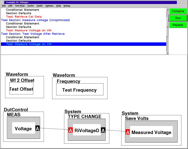
Retrieving the Cal Factor:
- Since this is not an RF port calibration or a Waveform calibration the calibration factor needs to be manually retrieved. This is done by introducing a Fixture Cal Factor source button into the test plan in which it is to be used. Also notice that a calc button "at freq:b" is utilized to load the data into a local variable. This re-establishes the frequency vs data format we need in order to use the data (fig. 6).
- The local variable can now be manipulated to pick out specific data. In this case the frequency was loaded into a local variable "Test Frequency" as well as the offset for WF2 "Test Offset" at 150KHz (fig. 7).
- A measurement was made using the WF instrument settings set to LV for the frequency and the offset ("Test Frequency" and "Test Offset"). The voltage value measured was the same as that recorded in the original calibration test plan (fig. 8).
Fig. 1 Fixture Definition
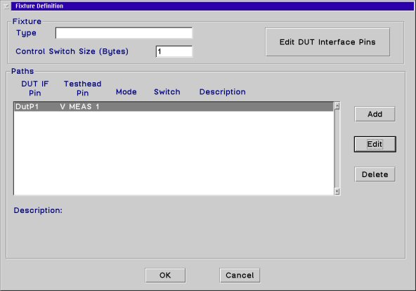
Fig. 2 Path Definition
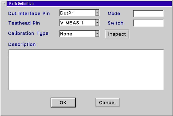
Figure 3 Reset Cal Data and load into Array LV
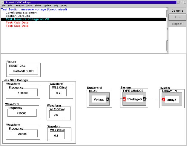
Figure 4 Add Frequency Axis
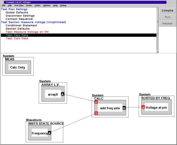
Figure 3 Reset Cal Data and load into Array LV
Figure 4 Add Frequency Axis
Figure 5 Cal Data Storage
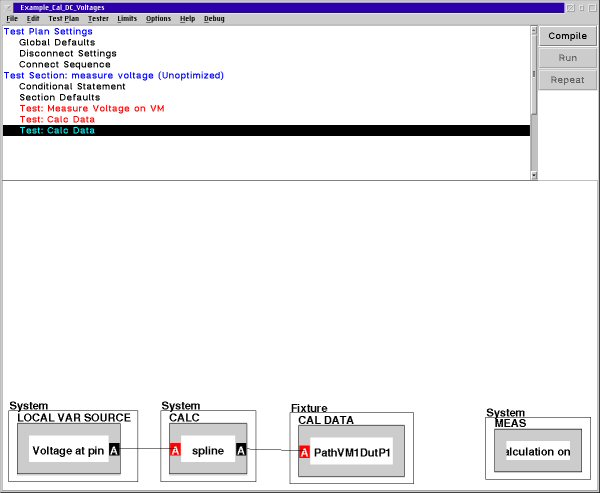
Figure 6 Cal Data Retrieval
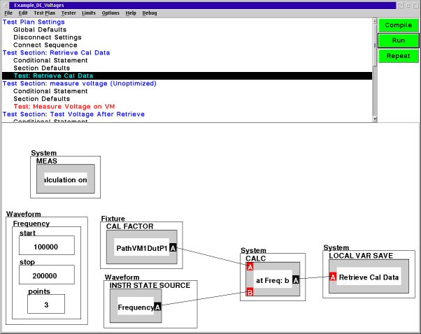
Figure 7 Load Data from Local Var into Local Var to be used
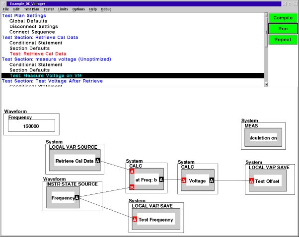
Figure 8 Using Cal Data as Waveform Settings