Fixture Debug Topics:
For fixture FAQs see this documnet 
Cal data has no affect on measured DUT data.
|
- Make sure calibration plan is storing data to the proper calibration factor.
For automated use the path name is case sensitive. It should NOT contain any "F". Only "f" should appear in the path name.
- Make sure calibration plan is resetting the proper calibration factor.
- Make sure the test plan is referencing the proper cal factor.
- Make sure cal data is being saved.
- Spefically on RF4 and RF5 of the Cassini platform. RF4 and RF5 are defined as from the testhead on the RI7100. On the Cassini they need to be defined in the device connection editor as from the tester.
|
S21 Cal Data/Test Data has spikes
in frequency response.
|
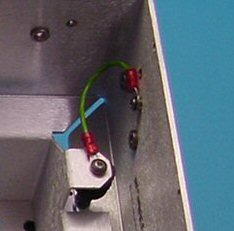
- Look for bad grounding or dirty connections/launches. Clean if necessary.
Fixture Cleaning:
Periodic cleaning of the RF connectors and fixture in general is
important. To clean the RF connectors:
- Choose a good quality Q-tip or cotton swab.
- Wet the swab in Isopropyl alcohol 90%. Then place the swab into the connector and twirl it once or twice only.
- Remove any cotton fibers left behind with tweezers or blow them out
with dry air.
- To remove debris from the Teflon insert, use a tooth pick or other sharpened instrument. Carefully wipe the insert being careful not to
put pressure on the center conductor.
- Any dust or debris inside the fixture is best removed by a stream of compressed air.
|
Noisy data at higher frequencies
(repeatable but varies a lot)
|
- Check to make sure test(s) are being done at optimum Receiver IF Gain
levels and power levels.
- Check to make sure the input and output ports are set up properly for the measurement.
- Check the physical RF connections.
|
| Noisy Data - not repeatable |
- Check the physical RF connections.
|
"Float Overflow" at compile
| 
- The test plan being compiled is relying on calibration data that is corrupt.
Make sure that calibration data being invoked is reliable.
|
"Key Is Missing"
|
- Sometimes if cal data is bad, it can cause this error. Please
check the tester/fixture cals to see if there is data in the
fixture that is not good.
- Check to make sure test buttons in test plan match path calls for the tester/fixture. This is especially is true of test plans copied from
other devices/fixture types.
|
Software button not working properly Cassini
Example - data not being reset or written over.
|
- When importing a calibration plan used on the RI7100 buttons need to be exchanged for those that work on the Cassini.
EX. Cal Data Reset button or Cal Factor Save Button.
(See Software) |
Modules not controlled
Further Debugging for the smart carrier |
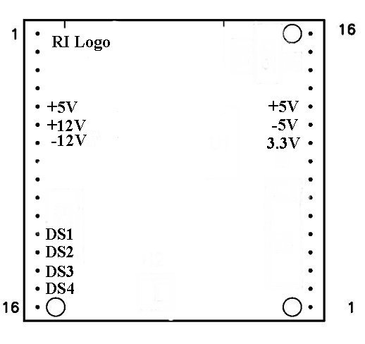
- Establish that proper operating bias is being presented to the module in question. To do this use a volt meter and verify the presence of voltages in accord with Figure 1 below. +3.3V will not be present on the Y0002AC1 carrier board.
- Check the four DS lines (DS1-4) that are used to control module
functions at each module location. These can be controlled from either
the tester controller directly or from a breakpoint in a test plan.
Note: For switch style modules only.
- Make sure the carrier board is configured properly for the module.
(See Modules)
- Make sure the 40 pin ribbon cable is properly seated on the bottom plate and the carrier headers.
- Run diagnostics on the testers Cbits.
|
Will Not Toggle
|
- Make sure you have properly selected the software carrier type for your physical carrier type. A Y0004VA1 carrier will not properly control the
Cbits if it is defined as a Y00065A1. To check what type of carrier you
have:
- highlight the activated fixture and use a RMBC.
- Choose "Inspect" from the pull down menu.
- In the listed attributes on the left hand side of the
inspection window, highlight the term "interface". This will tell
you the software definition of the carrier type.
- If they do not match perform a "Mutate" to the proper fixture type.
A carrier board marked 4VA must show Y0004VA1 A carrier board marked 65A must show Y00065A1
- If you have a Smart Carrier (Y0004VA1 or Y00065A1) the string code for Cbit control is of the format CXY where C is text, Xis the Cbit to be controlled, and Y is either 1 or 0 for state level. Older fixture definitions, copied from a passive carrier, will have to have the Cbit control strings changed to this format. They previously were of the format XXXXXXXX
with each X representing a Cbit state level.
- Check solder joints on back side of carrier board around cbit controller circuitry.
|
| Two device interface files active |
- One file is a copy of the other with both having the same physical
electronic serial number. Move the one not being used to a historical directory. Place the one that is being used into the devices directory under RIAPPS.
|
| Voltages sag or go to 0 V |
- Check module pins and make sure they are not bent.
- Remove modules until voltages go to normal. Fix or replace the offending module.
|
 | |
| Intermittent fails |
- Check pogo and cable connections for continuity.
- Ribbon cables from fixture bottom to carrier should not be more than 8" in length.
|
| Will Not Toggle |
Make sure the program listing in the module browser lists Y12JB13B not Y12JB13A for the RIK0017A. Program number should be Y18NA11A for
the RIK0127A.
Make sure module is in the M1 or M5 position only.
|
| Toggles at 400KHz (SPXP switch) |
- High Speed Digital is being used in M1 or M5 carrier board position. Change switch module position to M2-M4 or M6-M10.
- Remove HS digital instrument from E-Prom if not being used
|
Configuration for the RIK0017A:  Configuration for the RIK0127A:
Zero value for current
Current to high for VCC (testhead passes diags.) |
- Check pogo and cable connections for continuity.
- VCC5-8 (Cassini). Make sure VCCGS5-8 AND GS are attached to the DIB board.
|
 General Module Issues
| Modules are dead |
- Make sure that the software fixture is deactivated prior to installation or removal of the physical fixture.
|
| |
Intermittent
|
- Check pogo and cable connections for continuity.
|
Will Not Toggle
|
- Make sure the program listing in the module browser lists Y12JB13B not Y12JB13A for the RIK0017A. Program number should be Y18NA11A for
the RIK0127A.
- Make sure module is in the M1 or M5 position only.
|
Instrument buttons do not appear in editor/controller
|
configuration for the RIK0017A: 
Configuration for the RIK0127A: |
RF Path Loss
| Change in loss abruptly run to run |
- Check and clean the DUT socket.
- Make sure module is seated securely on the carrier board.
|
| RF path loss degradation over time |
- Check RF cables and connectors for breaks.
(See Also RF Path Loss - SPDT and SP4T Switches)
|
| Switch not turned on |
- Make sure module is seated securely on the carrier board.
- Make sure that the fixture power is turned on.
- Make sure that + / -5V appears at the switch pin header (pin 1= -5V and
pin 8 = +5V). For RIK0006B and RIK0026B.
- For RIK0056A, RIK0056B, and RIK0058A.
Establish that proper operating bias is being presented to the module in question. To do this use a volt meter and verify the presence of voltages in accord with Figure 1 below. +3.3V will not be present on the Y0002AC1 carrier board.

- Check the four DS lines (DS1-4) that are used to control module
functions at each module location. These can be controlled from either
the tester controller directly or from a breakpoint in a test plan.
|
| Switch will not toggle |
- Make sure the proper control bit (CBIT) or module control line is being controlled and is in the proper state. The normally closed position is active when the CBIT or control line is high.
- Make sure you have not shorted out, even briefly, the +/-5V supply for the fixture if it is actively controlled (active carrier type).
|
| Toggles at 400KHz |
- High Speed Digital is being used in M1 or M5 carrier board position. Change switch module position to M2-M4 or M6-M10.
- Remove HS digital instrument from E-Prom if not being used.
|
| High path loss when functional |
- Make sure the path has been calibrated properly.
|
| Ripple is very periodic |
- Try measuring at cardinal frequency points (calibration data points). If ripple goes away, increase the number of data points in the associated calibration routine (typically fixture related). This will allow the spline algorithm to work properly.
|
|
Change the receiver filter bandwidth from 7 KHz to 4 MHz to see if this affects the ripple.
|
| Unable to Read |
- Make sure you have a good ground connection between the fixture carrier and the test head. On new models of the fixture, make sure the grounding strap between the upper and lower halves of the test fixture has been installed.
- Make sure you measure short between the SN line on the carrier and the SN chip on the fixture bottom assembly (RI7100).
- When using the four SN chip board make sure ground (marked) is attached to the proper pin on the 2X5 header.
|
| Reads All 0s |
- Make sure that you measure an open between the SN line and ground. The SN will appear as all 0s when shorted.
|
| General |
- Make sure you have moved/copied the desired fixture to the D:\RIAPPS\fixtures directory (RI7100).
- Make sure the desired DIB is copied into the D:\RIAPPS\device directory (RI7100)
|
| No RiDibCal found for this esn: |
- Typically seen on a Cassini engineering fixture. Remove the SN chip from the back of the carrier. Two SN chips are competing. Typically encountered on the 6KA board when assembled as an engineering fixture.
- On an Engineering fixture make sure only one SN is active at a time.
|
| Unable to Save Test Plan |
- Make sure data save boxes are connected to data outputs.
|
| Test Plan will not compile/run |
- If the test plan was originally written for the RI7100 and you are attempting to use it on Cassini, you may need to replace Ri7100 compatible buttons with Cassini style buttons. (See Calibration)
|
| Test Panel Flags do not work |
- Make sure the flag data has been formatted. Also make sure the limits have been selected. Do not rely on copied buttons during panel creation. Use system copies only (editor).
|
| Shorted or Open |
- Make sure the DIB board clamp is not installed with out the DIB board itself. The clamp will short the pogo pins to ground.
- Make sure the pogo pin pad on the DIB is not shorted to ground.
- Check the pogo pin alignment to make sure that the pogo pin is not shorted
to the fixture top plate.
- Make sure that DC blocks have been provided on the RF pins. A short on an RF pin can draw down a DC pin voltage.
- Make sure the fixture is seated and docked properly on the test head.
- Make sure of continuity between the test head and the carrier board pogo pin. If the pin is attached to a Power VI make sure the cable connections on the
pin headers are installed and aligned properly.
- If the tester has an I_Drive capability (older tester) and the fixture is of new vintage then the I_Drive pin is being grounded by the fixture. Clip Pin#32
on header#1.
- Make sure the 40 pin ribbon cable is properly seated on the bottom plate
and the carrier headers.

- If the above suggestions do not resolve the problem, diagnose the test head
to make sure the resource is working. Make sure that the fixture power is turned on.
|
| Cannot measure correct voltage |
- If the pin is attached to a VCC or Static Digital Pin.
- Suggestion: Make sure the ground reference (GNDREF) and GND are connected to the desired ground.
- If the pin is attached to a Power VI.
- Suggestion: Make sure the VRTNS and RTNS pins are connected to the desired ground.
- If the above suggestions do not work measure the resistance from the bottom of the fixture to the pogo pin. This should not measure more than about 2 ohms. Reduce the contact resistance if it measures much more than 3 ohms.
- VCC5-8 (Cassini). Make sure VCCGS5-8 AND GS are attached to the DIB board.
- If the above suggestions do not resolve the problem, diagnose the test head to make sure the resource is working.
|
Tester Debug
| Measured power by receiver is lower than measured my power meter |
- Place tester into offending measurement mode and measure the DC voltage on the RF orts concerned at the test head. If a voltage appears then suspect on of the test head switches. Perform a test head diagnostic to find the offending switch.
|
| |
| Failure on First Run |
Check for strange setting buttons in the offending test section and panel.
For Example:
should look like this
|
Tester Warnings, Errors, and Failures:
Float Overflow
 |
- Sometimes if cal data is bad, it can cause this error. Please check the tester/fixture cals to see if there is data in the tester/fixture
that is not good.
|
| |
Instrument is Missing
| Instrument is Missing |
- Check the RIFL cable to make sure it is installed and not damaged.
- Test plan may be referring to a fixture instrument
(HS digital) that has not been configured on pre-configured on the fixture carrier.
|
| |
"RI Guru System Error-Invalid key/system
ID is missing" |
- The plug-n-play did not detect the hardware in the right
sequence at boot. This is OK,because the Guru system will check it again when you press OK and the Guru System will start without any problems.
|
| |
Patch Files
| "invalid patch file" |
- This error is usually the result of leaving a file in the "patch" directory that is not a patch. Any file that starts with "p21c", "q21c", "t21c", or "x21c" are assumed to be patch files.
EX. q21c.zip is not a patch file |
| Showing patch files |
- From the system message window click on Options -> Show Patches... then click on View.
|
Key is Missing
|
- Sometimes if cal data is bad, it can cause this error. Please
check the tester/fixture cals to see if there is data in the
fixture that is not good.
- Check to make sure test buttons in test plan match path calls for
the tester/fixture. This is especially is true of test plans copied
from other devices/fixture types.
- Make sure all device interfaces and DUTs are activated.
- Make sure that any instruments called for in a test plan are configured in the tester configuration window.
EX. Fixture HS Digital or Fixture Advanced I/O Buffer
- If nothing else works zip the VrtError.log file and send it to us.
|
| |
 |
- The error "logfilePrefix" can occur when a DUT is not defined
for the tester. It is not valid to run the tester with no DUT
selected. If a special DUT is not required, then "all duts"
MUST be selected.
|
| |
| RI Software opens automatically in simulation mode. |
- Check RIFL cable or Dongle.
- Check parallel port configuration
|
| |
| Port Not Set to Recieve S-param |
- Check port set up for proper measurement etiquette.

Example: When trying to measure S21 between RF3 and RF7.
|
| |
| Pout of Dut changes between testers. |
- Check the raw power required of the source to make sure it is between -15 dBm and +17 dBm (RI7100). To do this, set up a break point in the test plan and check the source power in the controller panel (Info Box).
Test Plan Panel for Displaying Raw Source Power
|
| |
| Fails to lock below 2GHz |
- Try replacing the A3 board with a known good A3 board.
- Change the down converter if the A3 board does not solve the issue.
|
| |
No Warning Hangs:
| Test Plan compile hangs when GPIB generic instrument is active. |
- Check to make sure the instrument has its own unique
address.
|
| |
| Test System Crashes after XXXX parts. Only recovers after reboot. |
- Check to make sure the "Details Worksheet" view is not opened while using the Test Exec. Memory will be overrun otherwise.
This can be done from the "Options/Start up..." menu of the test exec.
|
| |
Handler Pods:
| Improper bining / no EOT |
- Confirm good cables by substituting in a know good pod.
- Confirm proper configuration for the suspect pod. Compare with known good pod.
- Replace cables and check with a know good pod.
- Confirm proper settings on handler configuration.
|
| |
https://roos.com/docs/DFES-7Q8U4Y
ROOS INSTRUMENTS CONFIDENTIAL AND PROPRIETARY
©2009-2025 Roos Instruments, Inc. All rights reserved.

