

This document describes how to identify defective Cassini16 Testhead "Latch" problems and repair internal spring assembly. A 4 inch spring length is used where a 3 inch length spring is required. A work around to prevent production downtime, apply slight downward force when Latching the Fixture.
This non-critical flaw may affect up to 4 systems shipped after 7-1-2014 and before 8-18-2014 (S/N: GCA9X5YA, GCA9WMYA, GCA9WTYA, GCA9WZYA). The infrastructure uses these springs to latch and unlatch the Fixture, no performance or feature degradation is possible with the affected parts. Due to the low impact of the flaw, proactive customer notification was deemed unnecessary.
URGENCY: Very Low
SYMPTOMS
Spring may come disconnected in the Testhead "canoe" assembly, requiring the Fixture to be pressed down for the latch light to turn green. Only one or both assemblies could be affected.
IDENTIFYING DEFECTIVE SPRINGS
Center conductor sticks out is not low enough. Height can be inspected with the QuickLock DIB assembly removed and without disconnecting or unscrewing Insert from Fixture TOP Plate. Dial calipers can be used to inspect height to be between 0.008-0.015 inches over grounding squares as illustrated.
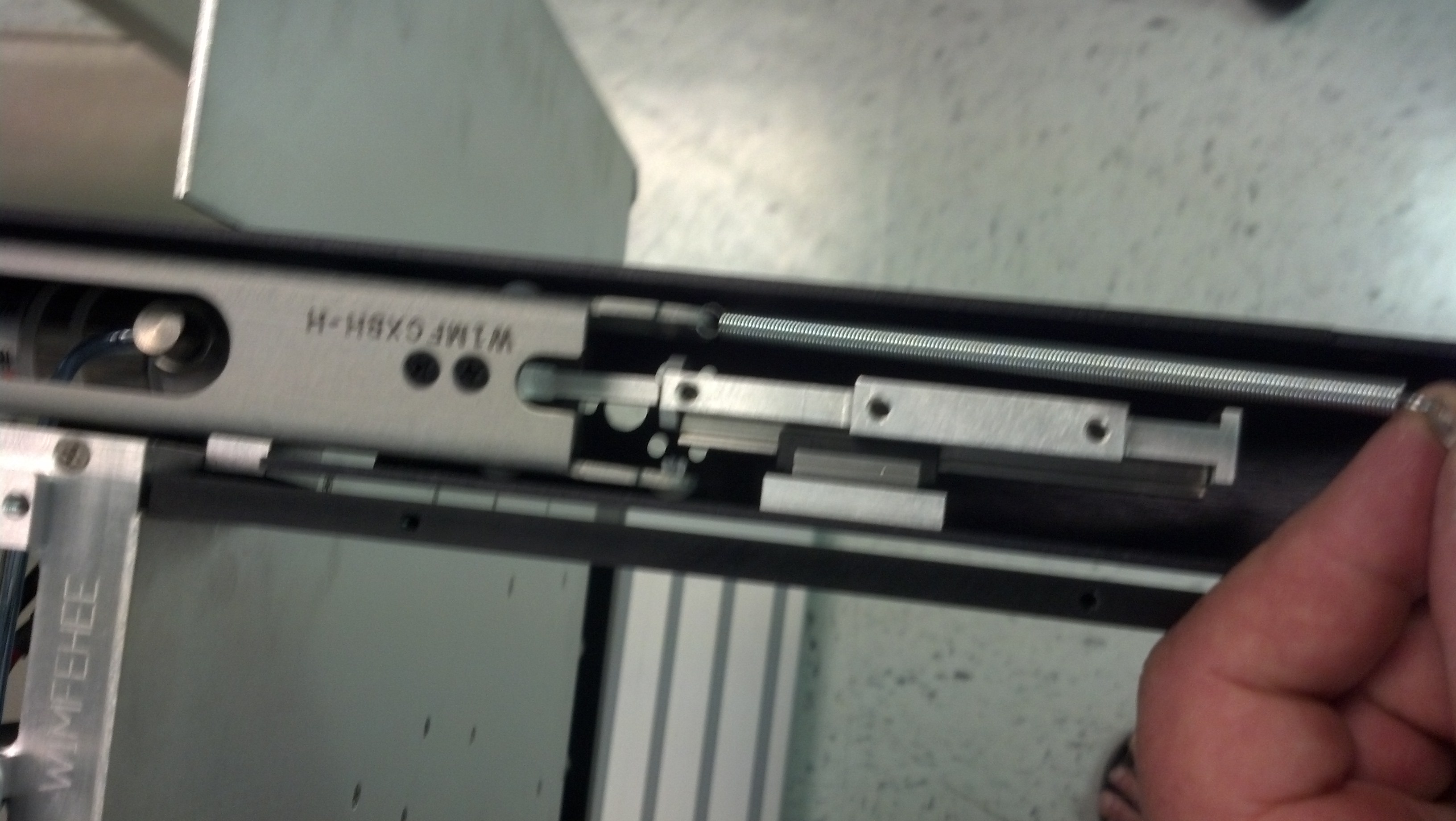
DEFECTIVE SPRING: Notice 4 inch length. Defective bent or broken solder lug.
CORRECT INSERT: Notice 3 inch length. Correctly bent solder lug. Part Numbers: M6JKAEJ3A (solder lug used as mounting tab) MG6XJB6A (3" extension spring)
CORRECTIVE ACTION REQUIRED
If any defective springs are identified, replace each by removing the Top Plate and Side bars. Requires 1/4" wrench, #2 philips screw driver, Needle nose pliers. Remove defective spring and replace with good assembly. Remove the Testhead service panel of Cassini (See ![]() Advanced Troubleshooting - Cassini 16 Infrastructure (RI8568B)). Contact RI Support ([email protected]) to exchange defective units and return to RI Factory via standard RMA procedure.
Advanced Troubleshooting - Cassini 16 Infrastructure (RI8568B)). Contact RI Support ([email protected]) to exchange defective units and return to RI Factory via standard RMA procedure.
These pictures can assist with replacement.
 IMG_20140818_090747_171.jpg
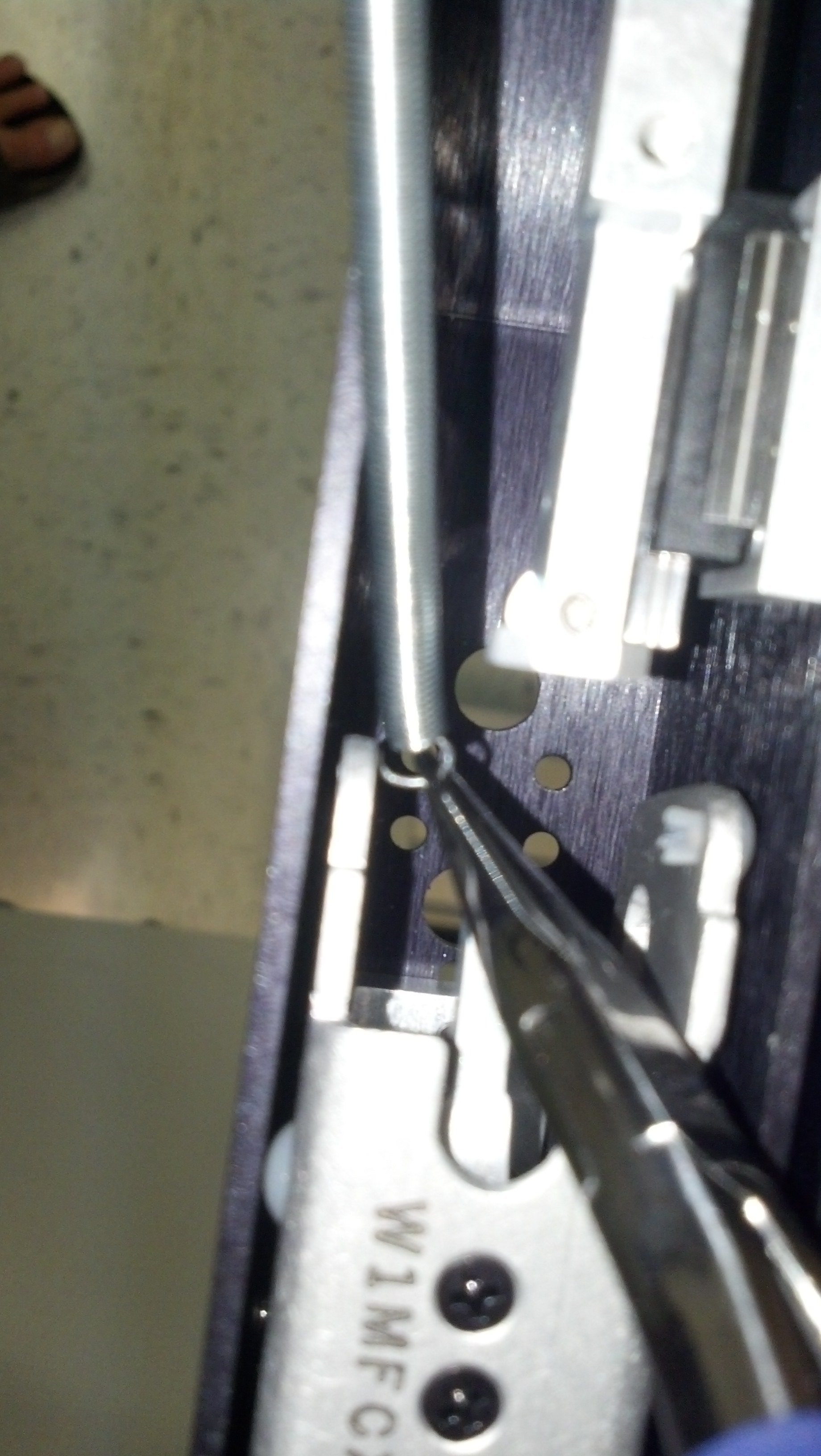 IMG_20140818_091039_115.jpg
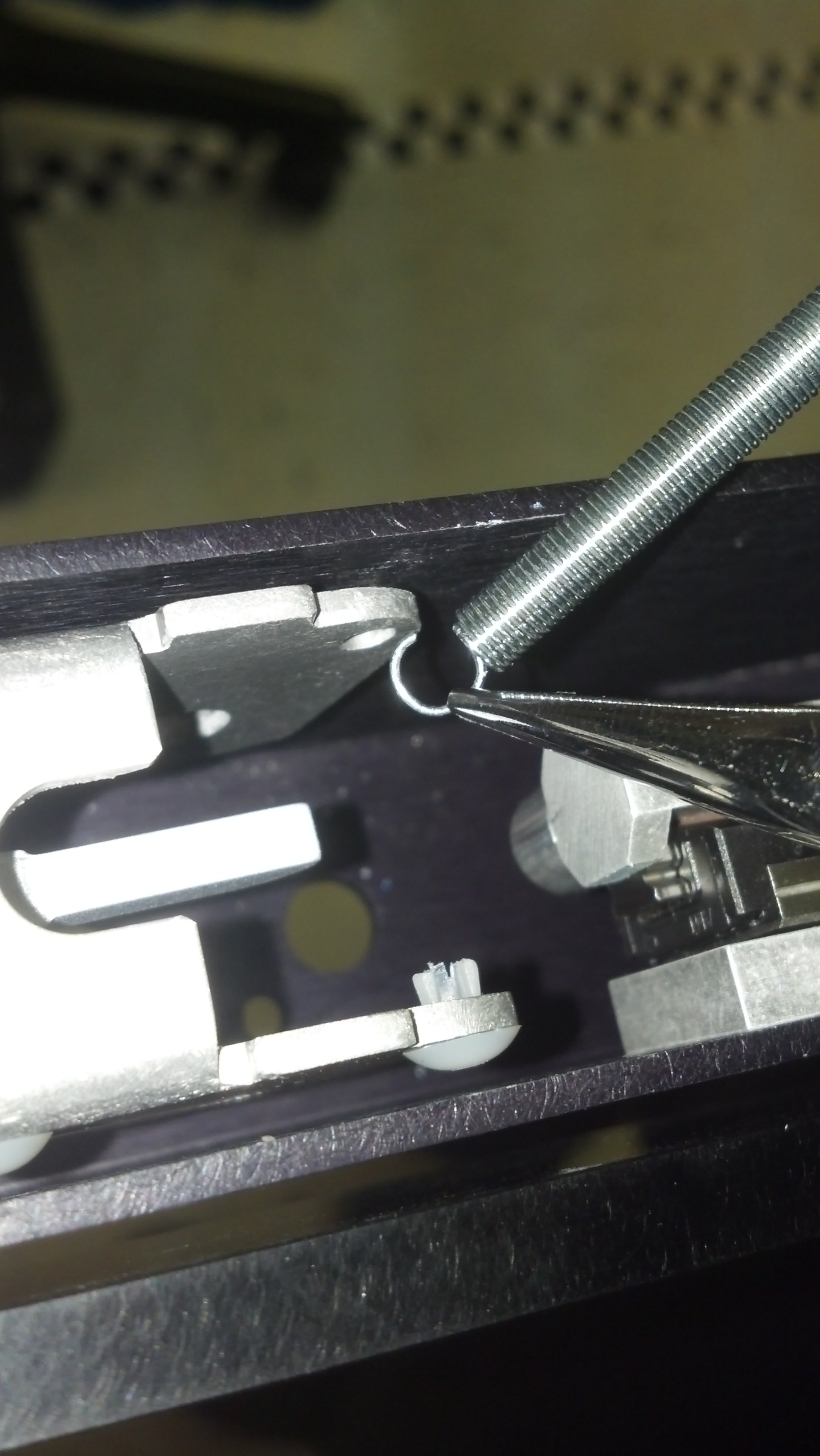 IMG_20140818_091907_991.jpg
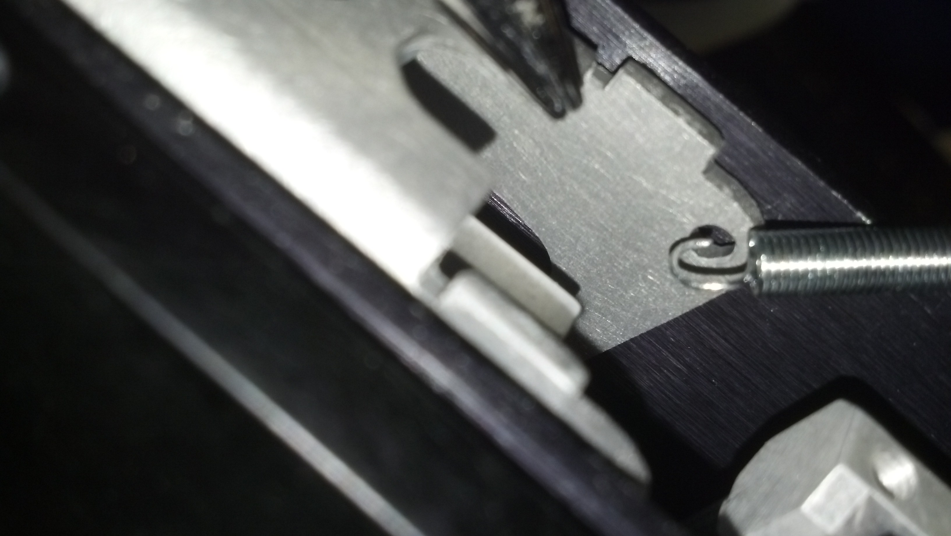 IMG_20140818_091932_929.jpg
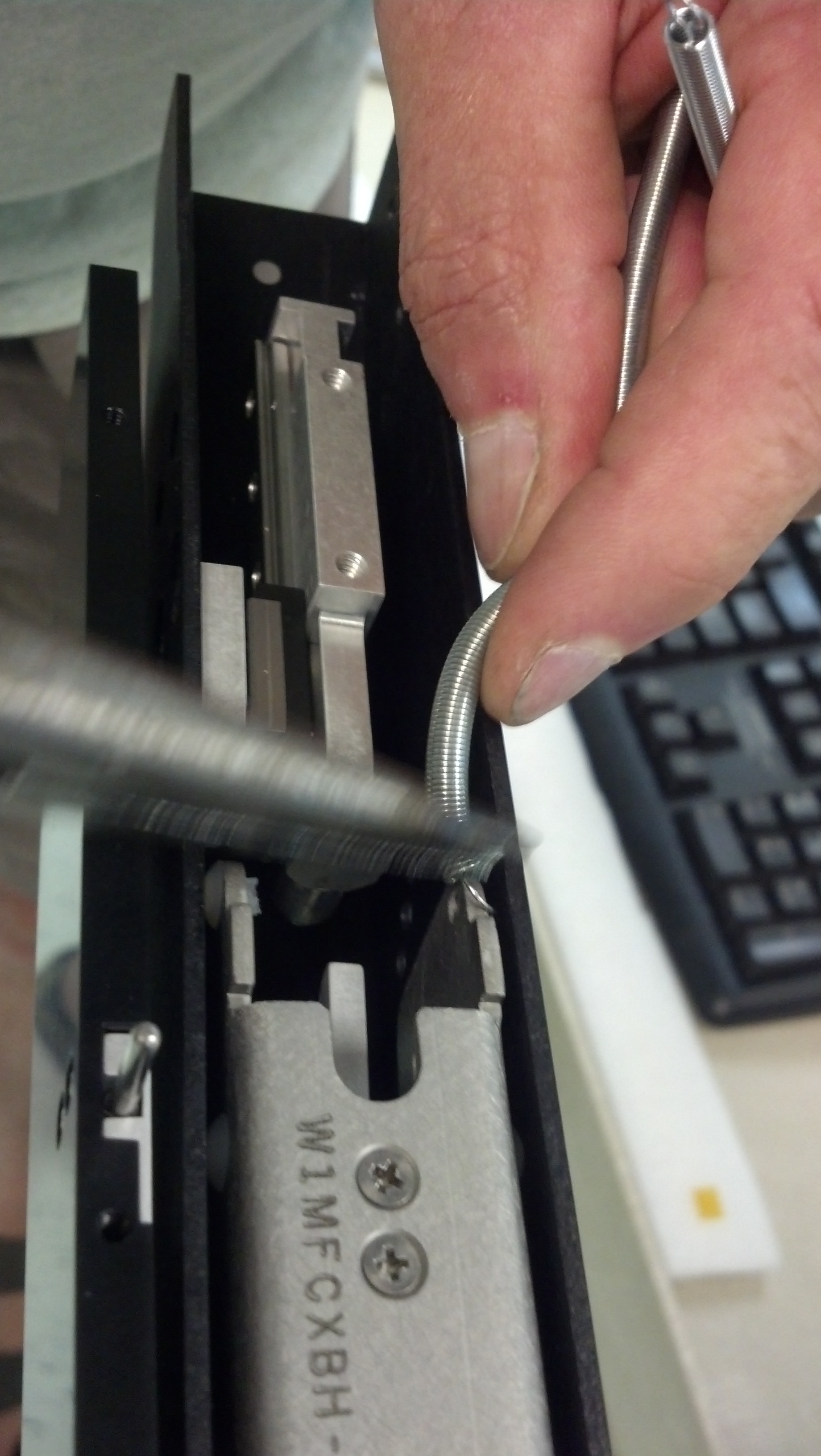 IMG_20140818_111016_965.jpg
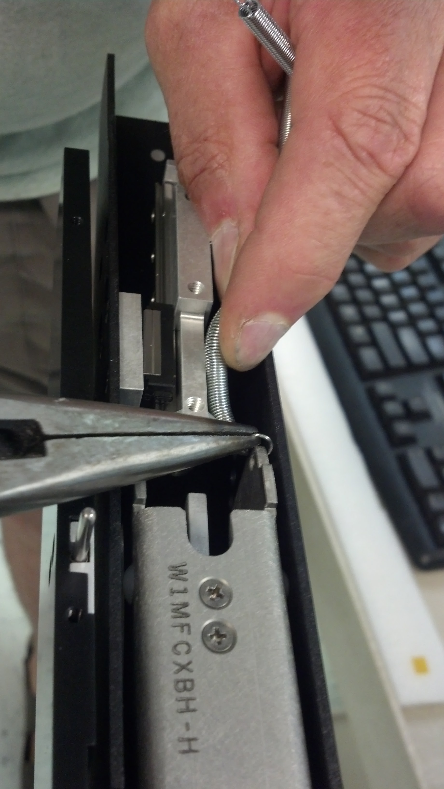 IMG_20140818_111020_185.jpg
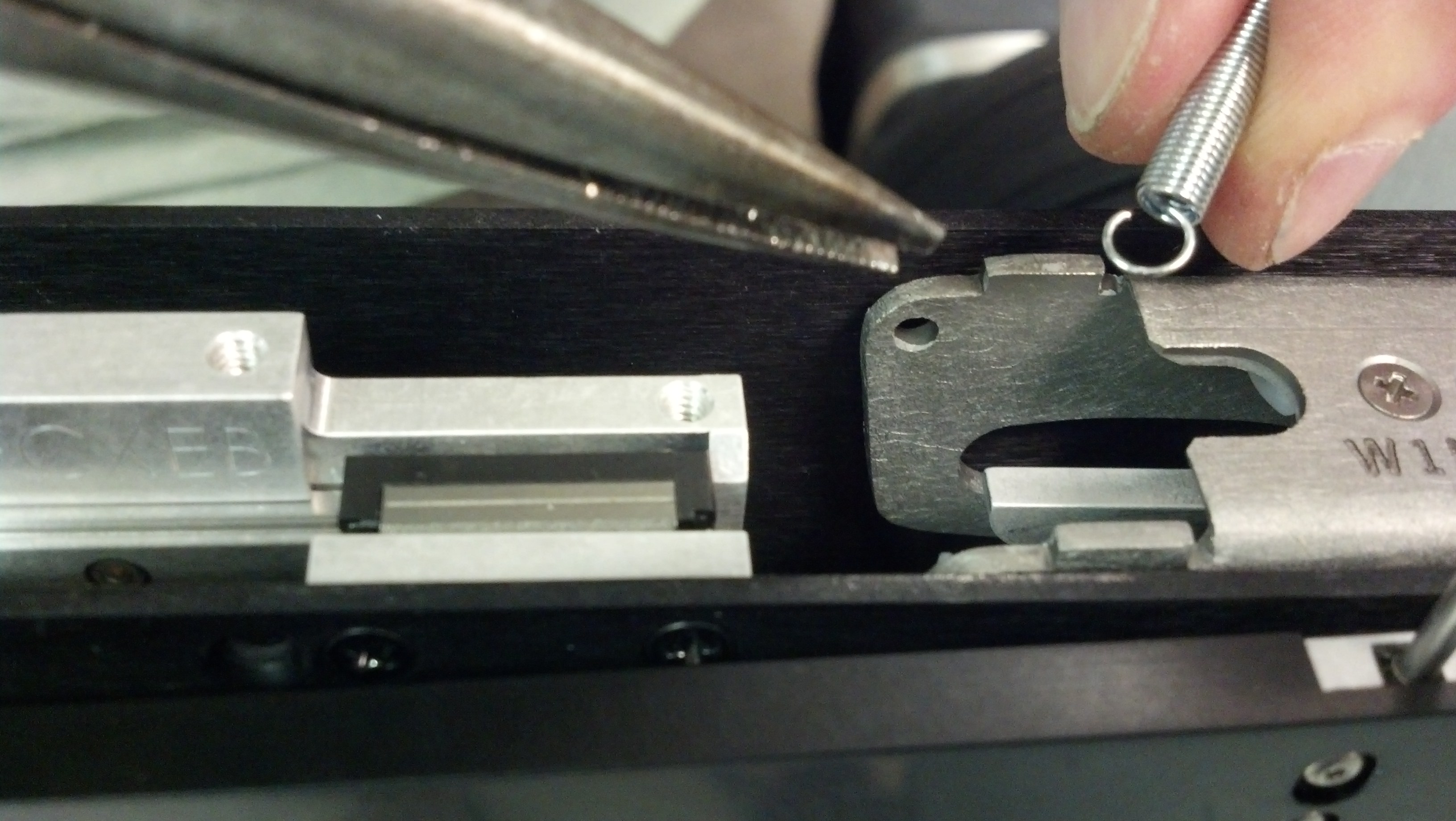 IMG_20140818_111139_533.jpg
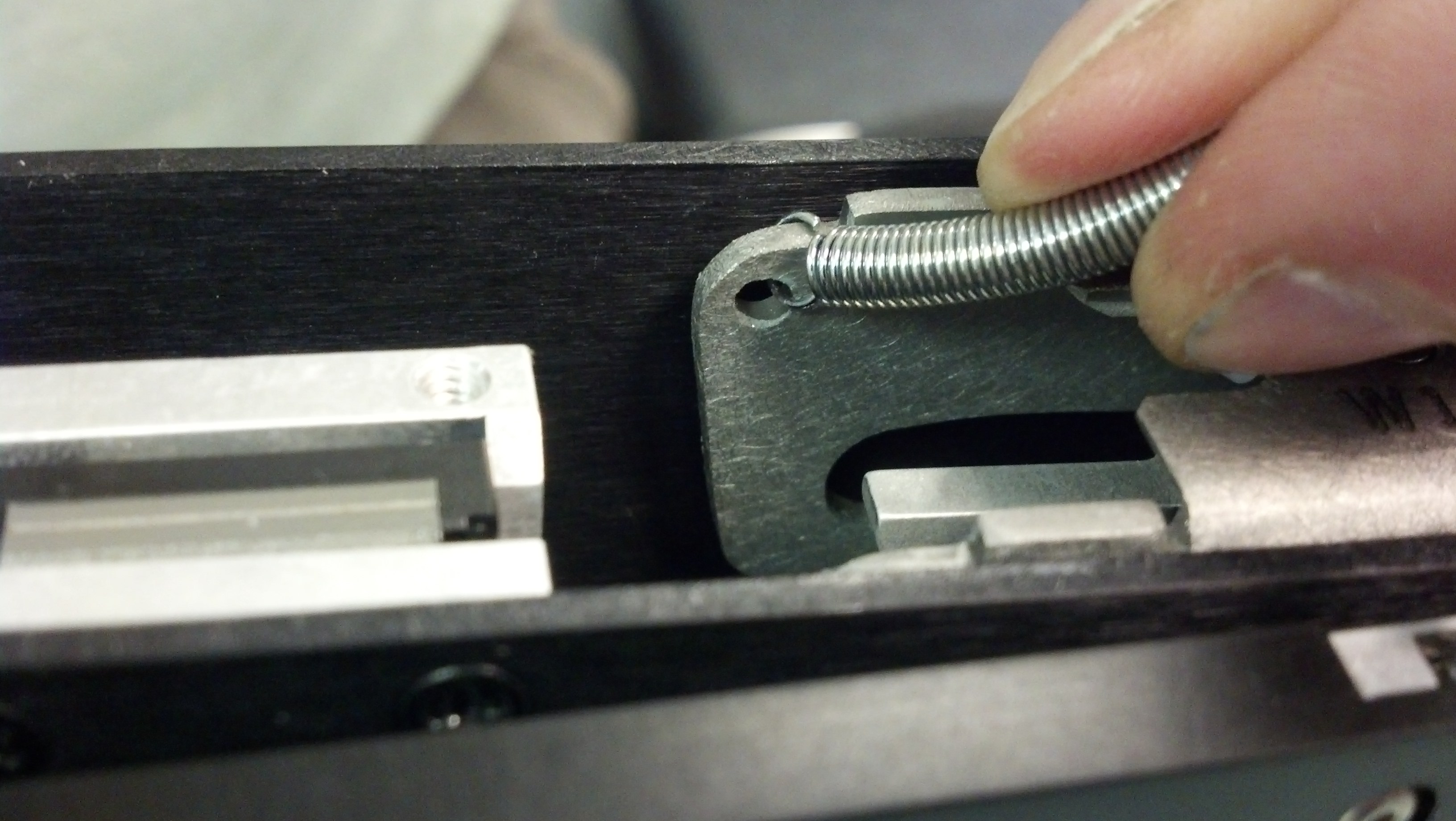 IMG_20140818_111154_241.jpg
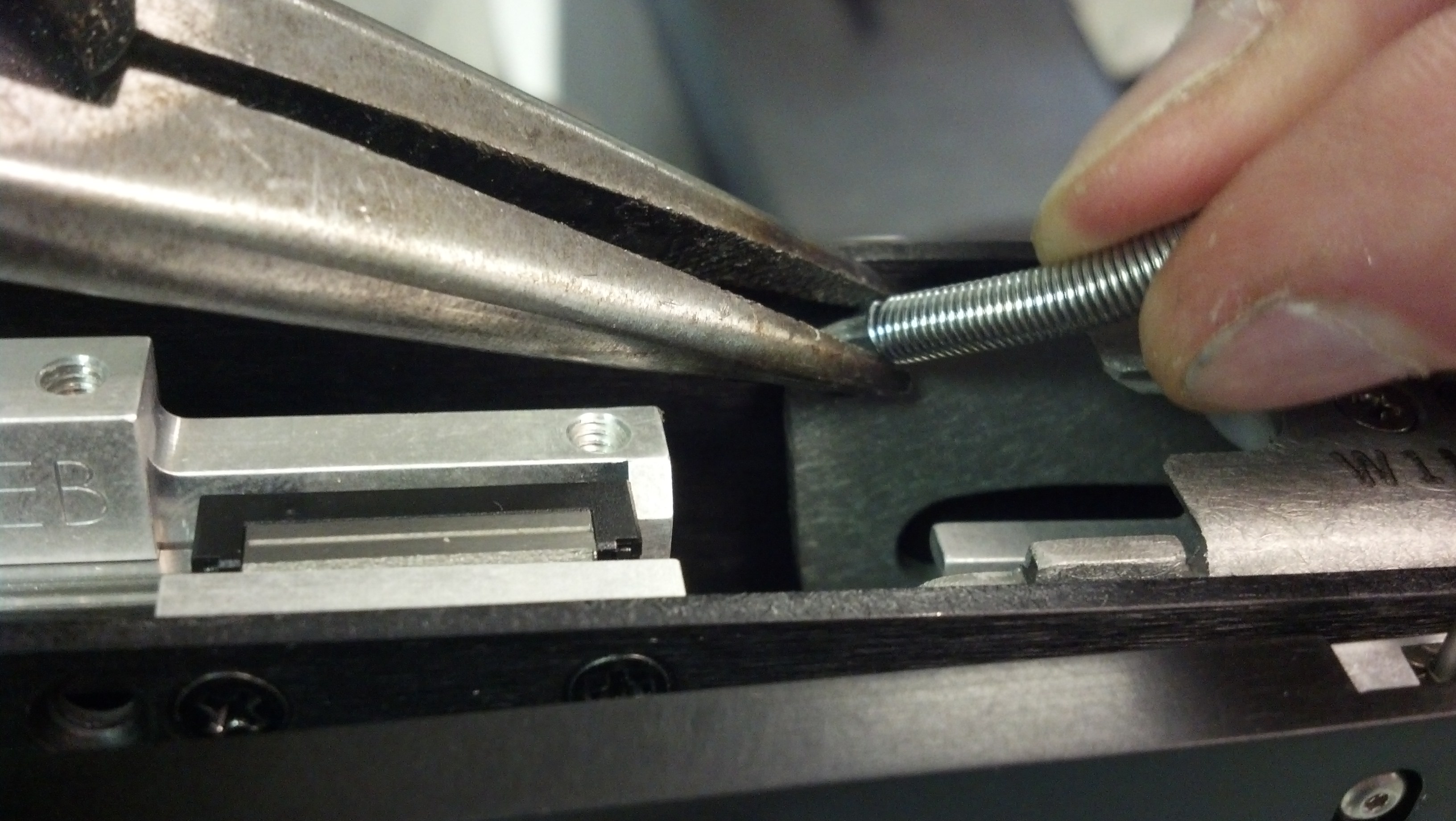 IMG_20140818_111158_605.jpg
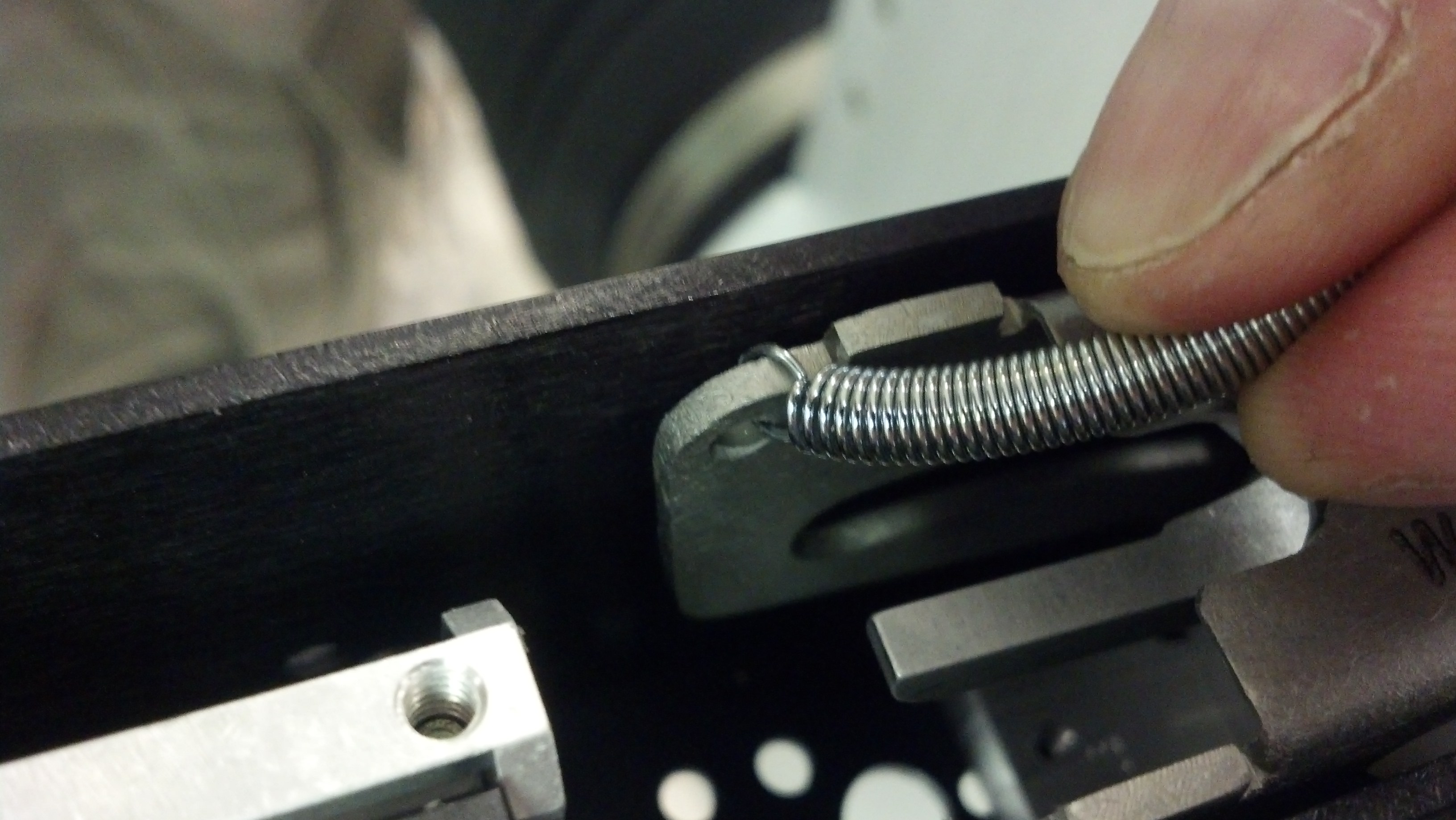 IMG_20140818_111204_389.jpg
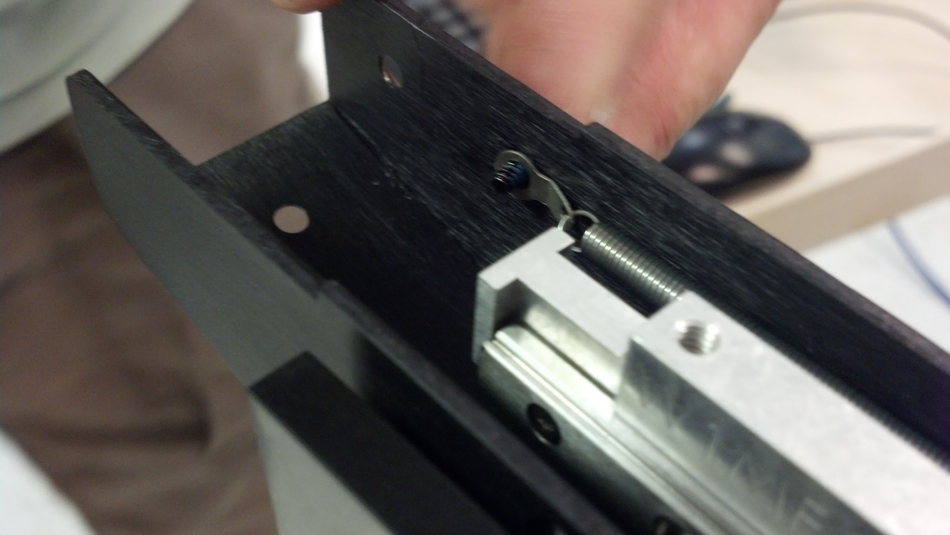 IMG_20140818_111237_134.jpg
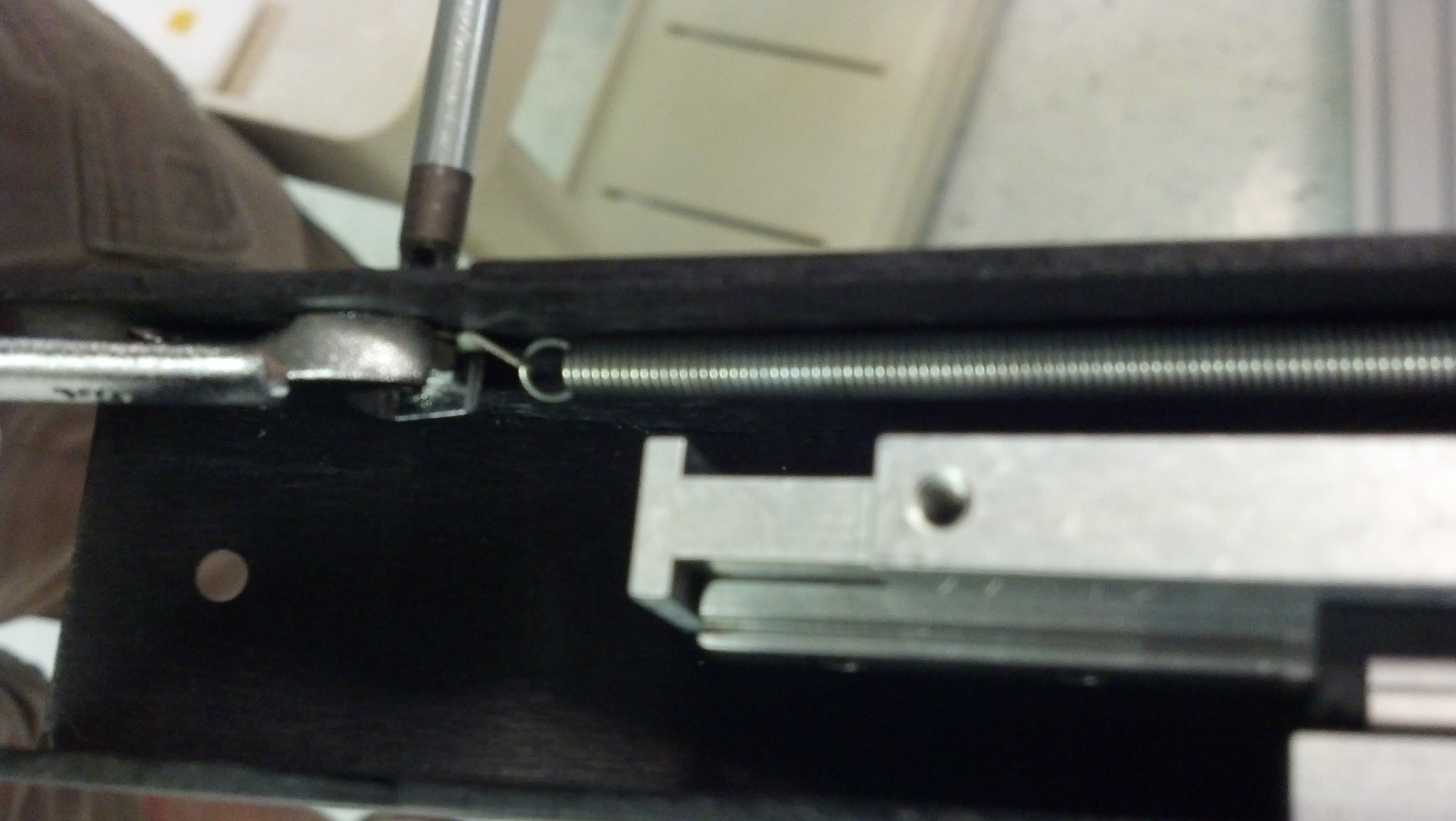 IMG_20140818_111302_773.jpg
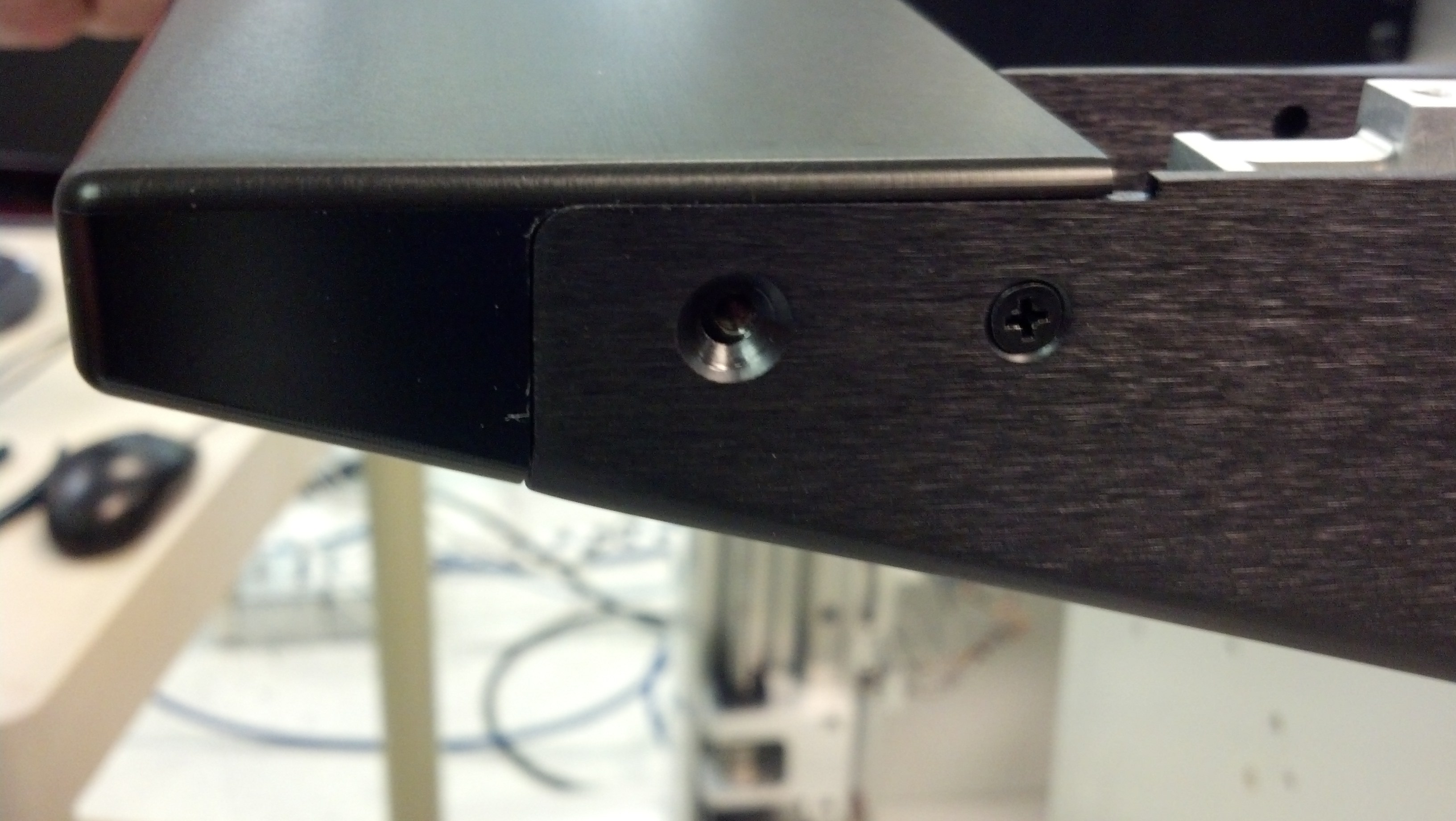 IMG_20140818_111335_546.jpg
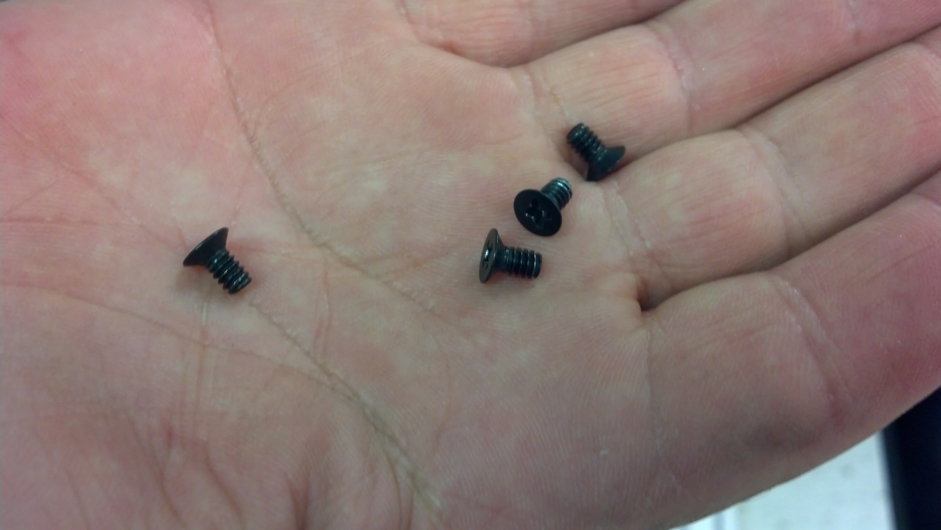 IMG_20140818_111339_491.jpg
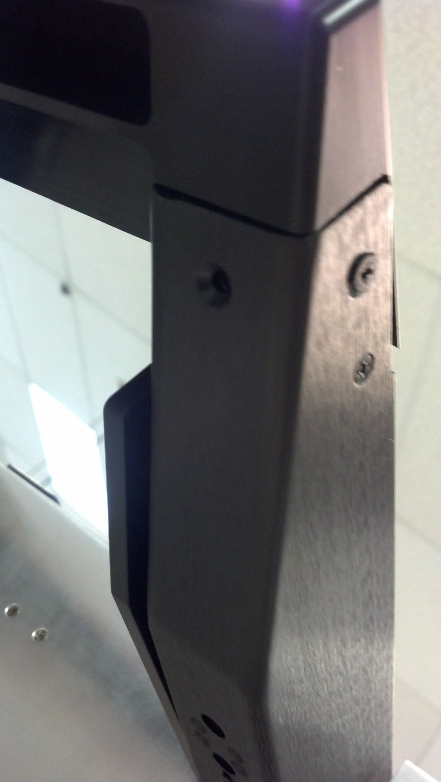 IMG_20140818_111357_343.jpg
These instructions detail how to remove the Top Plate and replace the Top Board. Contact Support ([email protected]) for specific instructions for diagnosing or replacing malfunctioning items.
IMPORTANT: POWER DOWN THE SYSTEM CONTROLLER AND REMOVE ALL TIMS BEFORE DISASSEMBLING THE TESTHEAD!
Tools Needed:
#1 Philips (All Panels)
There are NO electrical shock hazards from any of the exposed electrical connections on the test head or on any surface of the system. The system uses 48 volts or less and shock hazards are typically designated as to 50 volts or higher. No high-voltage cables or connections are exposed at any time during operations or when moving the system. Fixtures and Tester Instrument Modules (TIMs) can be safely removed "hot" without disconnecting power without damaging the equipment or exposing live connections to the operator. The system is equipped with an Emergency Off (EMO) button that instantly disables all 48 volt connections.
The "Main Breaker" is used to disconnect all electrical connections and should be switched "Off" before performing any infrastructure maintenance that requires tools to remove protective metal covers. The side breakers labeled "TIM Front", "TIM Rear", "Head" or "Mainframe" can be switched "Off" before opening specific service panels. The System Controller MUST ALWAYS be properly powered down BEFORE switching off any breakers. IMPORTANT Switch the "TIM Front" & "TIM Rear" (RevA) or "Head" (RevB) side breakers to OFF before opening the Testhead service panel.
Testhead Top Removal
- Diagram A shows the 16 screw locations needed to remove the access panels for either the Testhead or Front panel, 3 on the back, 12 on the top, and 3 on the front. Remove ALL TIMs and rotate the top of the Testhead away (as pictured).
- With the side cover removed, you can access the connectors on the top boards. Unplug 2 power harnesses, one from the front and one from the back, and unplug 2 flat ribbon cables, one from the front and one from the back. Note that you do not need to remove the harness that goes to the center block.
- Now, with the testhead straight up, begin removing screws from the top of the Testhead. There are 8 ea. 4-40 screws that hold the top plate to the lower assembly (also called the 'canoe'). There are 8 ea. 6-32 screws that hold the linear bearings inside the canoe. And there are 8 ea. 8-32 screws that also need to come out. With all the screws removed, you should be able to lift the top plate straight up.
- Remove the top plate and "Side Bar" ...
CHRIS: Add instructions and pics here
To install, reverse the process as follows:
- Screw the new board to the top plate with the 3 screws.
Note: As you prepare to set the top plate back on the canoes, note that the linear bearings need to align with the holes. They should not have moved but, if they have, you may have to adjust them as shown in Diagram B (above). Also note that there are 2 alignment "Joist Pins" that need to go through holes in the top plate. When you set the top plate on the canoes, you will need to make sure these pins go through the top plate's holes. - Now carefully set the top plate back onto the canoes, keeping in mind the notes above.
- Install the 6-32 screws into the linear bearings first. These screws must be started by hand. If you are using a power driver, start the screws by hand, then you can power them down. Next, install the rest of the screws in the top cover.
- Plug in the power harnesses and flat ribbon cables to the boards. Re-install the side panel.
- Plug the TIMs back in. Power the tester up and confirm that all the TIMs now work by running Diagnostics.