The RI7100A has optional capability to provide AM, FM, and phase modulation for source 1 (Option 006). This document describes how the FM can be used to provide Frequency Shift Keying (FSK) modulation and the limitations that apply.
FM capability on source 1 allows FSK modulation, if the rate is high enough and if the pseudo-random bit stream (PRSB) doesn't contain too many ones or zeros in a row.. (For further information on the RI7100A's BER measurement capability, reference the document Setting up BER Bit Error Rate Measurements on the 7100A Test System.)
When you FM a synthesizer, the FM and the phase lock fight each other. The FM is trying to make the signal move but the Phase Lock Loops (PLL) are trying to keep the signal from moving.
The way to avoid this is to FM at rates higher than the bandwidth of the phase lock loops (PLL). That is why there are 2 FM modes in the 7100A. In the mode 'FM', the bandwidth of the PLL is wider, which results in good phase noise, but the minimum rate for the FM is 50 kHz. In the '1kHz FM' mode, the PLL bandwidth is narrowed to <1 kHz. This makes the phase noise of the source slightly worse, but now you can FM at rates down to 1 kHz.
| Mode | Rate (sine wave, 3dB BW) | Max Mod Index | F Noise |
| FM | 50 kHz to 10 MHz | 3 | Standard |
| FM 1 kHz | 1 kHz to 10 MHz | 300 | Degraded |
Although it's not exactly the same thing, a reasonable approximation is to think of the FM input as being AC coupled through a small coupling capacitor that only passes higher rates.
In true FSK, the output is switched between 2 oscillators at different frequencies. To simulate FSK with FM, the frequency is slewed between 2 frequencies. With the source's maximum FM rate of 10 MHz, the source can slew very quickly between the 2 frequencies, providing a good simulation of FSK.
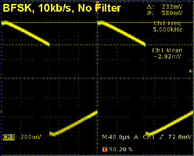
For FSK, the modulation is essentially a square wave. If the rate is too low, the frequency will 'droop' toward the middle when you'd like it to remain flat. (Think of a square wave through a capacitor.) The following figure shows the demodulated output from source 1, using '1 kHz FM' mode, while applying a 1010 pattern at 10kb/s. Note that there is significant droop in the pattern.

Demodulated Signal, 10kb/s, bfsk modulation
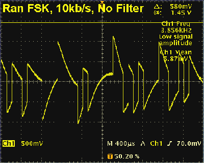
The droop becomes worse when a random pattern is used because there may be several 1's or 0's together. The following figure shows the same demodulated output using a random FSK pattern at 10kb rate. As you can see, this pattern would not be usable at these settings.

Demodulated Signal, 10kb/s, pn7
As a rule of thumb, to graurantee no droop, 1/minimum frequency must be at least 20x the maximum time the signal spends at 1 or 0. For example, using the 'FM 1 kHz' mode, the minimum frequency is 1kHz. 1 / 1kHz = 1ms. 1ms / 20 = 50us. So, to operate properly, the pattern can't stay at 1 or 0 for more than 50us.
Taking that further, a pn7 pattern can have as many as seven 1's in a row. 50us / 7 = 7.14us. So, for a pn7 pattern, a bit can't be more than 7.14us, which translates to a bit rate of 140kb/s for no droop.
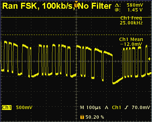
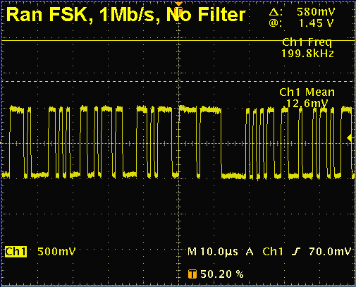
That number could possibly be lowered somewhat, depending on the tolerance of the DUT to offsets. The following images show a pn7 pattern at a 100kb/s rate and at a 1Mb/s rate. Note that the 100kb/s rate shows some droop that may, or may not, be acceptable depending on the tolerance of the DUT. At the 1Mb/s rate, there is no droop at all.

Demodulated Signal, 100kb/s, pn7

Demodulated Signal, 1Mb/s, pn7
Here are some typical specs for the FM capability. Note that these specs are for reference only. For complete, up-to-date specs, refer to the RI7100A specifications.
FM Modulation
Modulation Input: Testhead WF5
FM Sensitivity: Variable from ±10 kHz per volt typical to ±20 MHz per volt typical
Input Impedance: 600 ohms
Accuracy: (100 kHz rate): 10% typical
1kHz FM Mode:
Rate (sine wave): 1 kHz to 8 MHz
Deviation: The lesser of ±10 MHz or rate x 300
FM Mode:
Rate (sine wave): 50 kHz to 8 MHz
Deviation: The lesser of ±10 MHz or rate x 3
Special note about sensitivity and input impedance: The FM is calibrated to be accurate when used with the waveform generator. For example, if the sensitivity is set to 1 MHz/volt and the waveform generator is set to +/-1V, then the FM will be +/- 1 MHz. However, because of the FM input's 600 ohm input impedance, the actual voltage at WF5 will not be +/-1V, it will be slightly less than that. The numbers all add up when the FM is driven from the waveform generator, but this difference must be considered if driving it from any other source.
Keeping the above considerations in mind, the RI7100A's source 1, with the optional FM modulation, can create FSK signals.

