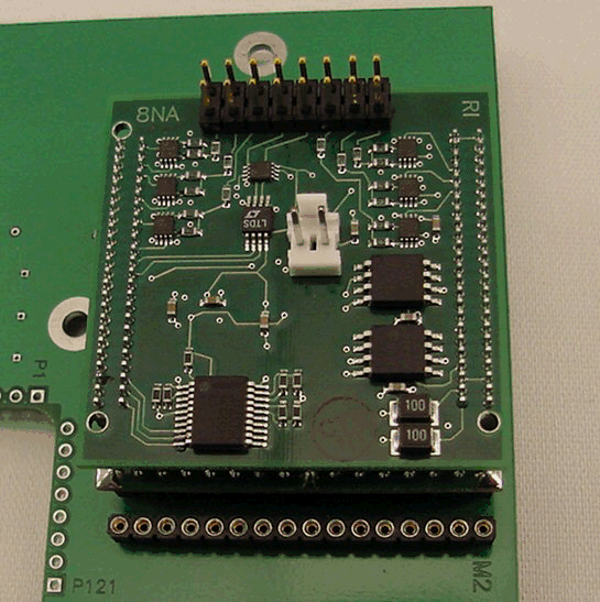
Improved physical interfaces for easier integration than RIK0017A. Adds Scan and 16 MegaVector memory depth. Use RIK0148A Digital Coax cables ONLY. DO NOT USE DC JUMPER WIRES.
Provides High Speed (Up to 80 Mbits/sec.) Digital control signals to the DUT from the fixture.
Top Board: = Y0008NA1

High Speed Scan Module Kit (1 Module)
2 Sets of 4 I/O Pins: DB 1 to 4 and DB 5 to 8
Von and Voff Set Range: 0 to 4V
Vcompare: 0 to 4V
Serial Control Supports: Data Read, Data Write, Clock, Strobe
Serial Write: Up to 80 Mbits/sec.
Scan Support: Yes
Parametric Measure: Yes
Y0008NA1 HS Digital Scan Pin Out
Pin# | Function | Note: | Connector Type |
P1 | Configurable | Data, Clock, Strobe, or Static | Header Pin |
P2 | Configurable | Data, Clock, Strobe, or Static | Header Pin |
P3 | Configurable | Data, Clock, Strobe, or Static | Header Pin |
P4 | Read A | Header Pin | |
P5 | Read B | Header Pin | |
P6 | Configurable | Data, Clock, Strobe, or Static | Header Pin |
P7 | Configurable | Data, Clock, Strobe, or Static | Header Pin |
P8 | Configurable | Data, Clock, Strobe, or Static | Header Pin |
P9-16 | GND | ||
H4-1 | GND | Header Pin | |
H4-2 | MUX I/O | Header Pin |
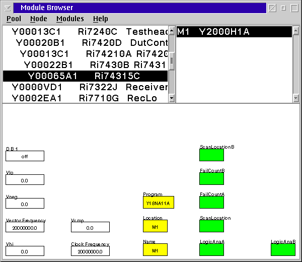
Configuration Window Settings:
Module = Y2000H1A
Inst#: RI74315C
Program = Y18NA11A
Vlo = 0
Vneg = 2
Vector Freq = 80000000
Vhi = 0
Vcmp = 4
Clock Freq = 20000000
DB1 = off
Scan Location B = blank
Scan Location = blank
NOTES:
- Module will only work in M1 or M5 positions of the carrier board.
- Keep 40 pin ribbon cables from fixture bottom to carrier less than 8".

Configuring the Carrier:
Scan Requirements:
tbd.

