

RI PC Board Replacement Procedure
If a PC board "module" has been determined to be failing, then replacement is needed. Utilize the Carrier board layout and Carrier connection schematic diagrams in the training manual for Test Head Modules, and section 16 of the training manual for SRC 1&2 Output Matrix Module, to locate the failed board. Obtain a replacement by contacting RI for shipment of a replacement board. Then follow the following instructions for replacing modules.
NOTE: The pins on the boards are very delicate and extreme caution should be used when handling, removing or inserting any of the boards.
1) Turn off the DC power to the Test Head by opening the back door of the RI 7100A rack and turning the switch on the back of the bulk DC power supply (located at the bottom of the rack) off.
NOTE: Check the power light on the test head and make sure that it is NOT illuminated!
2) Remove any Test Fixture from the Test Head and turn the Head so that the pogo pins are facing downward.
3) If the module is located on the Test Head bottom carrier then remove the 16 screws along the side and bottom that secure the bottom cover. Unplug the Test Head fan connector while carefully lifting off the bottom cover. Proceed to line #5.
4) If the module is located on the Test Head Top carrier then support the Test Head on a cart or table and remove the 12 small Phillips head screws from the top section of the Test Head, including the 4 screws in around the pogo ring.
CAUTION: Securely hold down the test head cover as you remove the last screws. Without the weight of the test head, the cover can spring upward.
Carefuly raise the manipulator arm away from the supported Test Head.
5) Examine the printed circuit board(s) and find the module(s) that need to be replaced.
6) Note the orientation of Pin 1 on the Module (see Figure 1) and location/orientatoin of any attached cables.
TIP: Make a sketch and label each connector you removed.
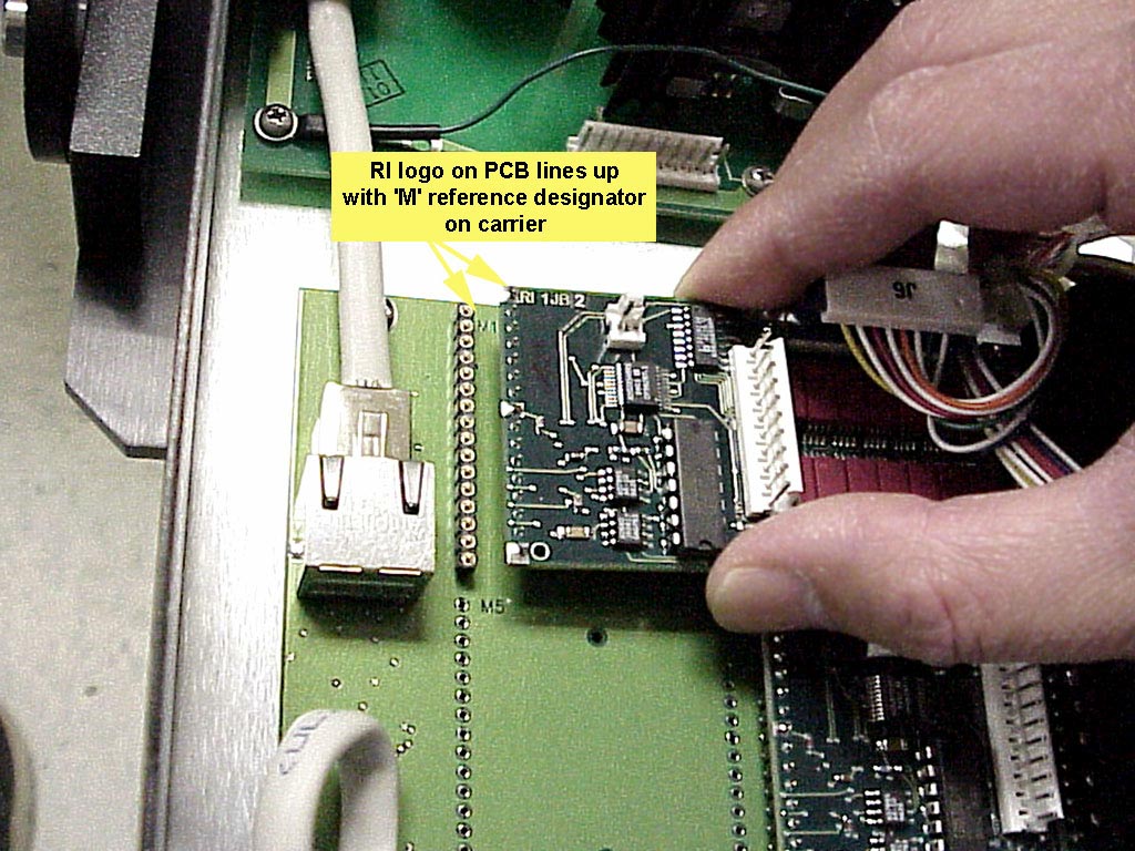
Figure 1
7) Wearing a ground strap that is connected to the Test Head ground connector, slowly remove the module(s) as shown in Figures 2 and 3.
NOTE: Be careful not to break or bend any of the delicate pins on the modules.
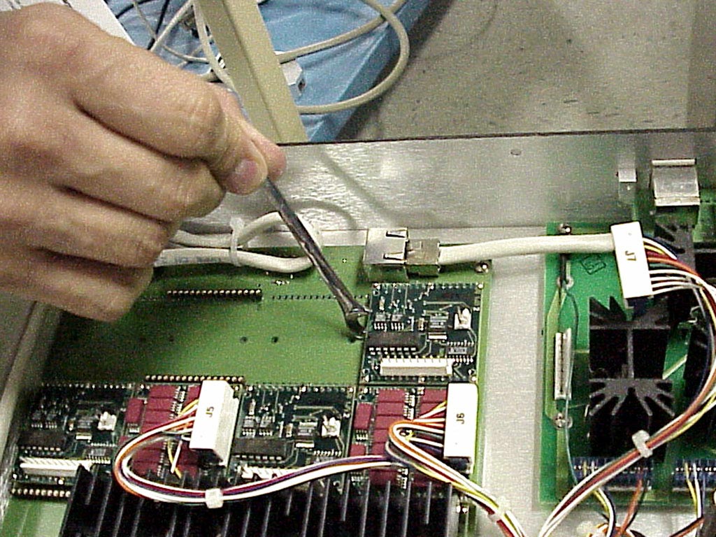
Figure 2
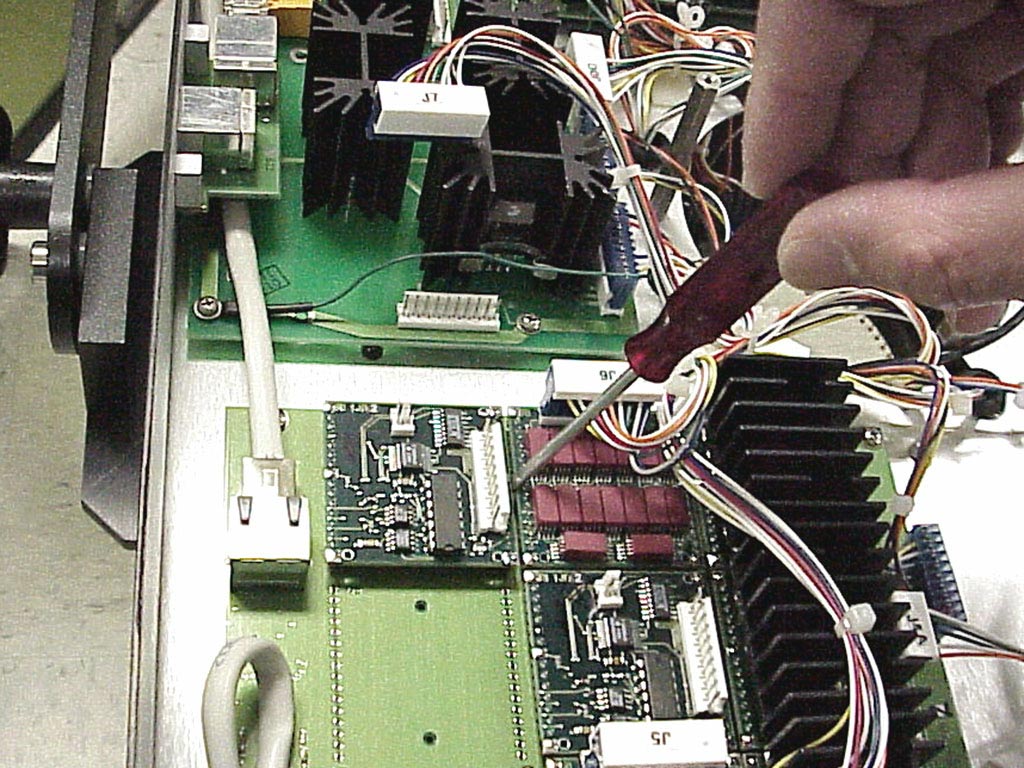
Figure 3
8) Identify pin 1 on the module(s) and on the carrier board (see Figure 1).
NOTE: Inspect the replacement module(s) for bent or missing pins before installing.
9) When installing the new module, check to make sure all of the pins of the replacement module(s) are properly aligned with the mating socket on the carrier board. Carefully push the module(s) straight in. Make sure all the pins are properly seated.
10) Reinstall any cables removed from the module(s) and double check the orientation of pin 1 on all the modules.
11) If the module was located on the Test Head bottom carrier, then plug the bottom cover Test Head fan connector in while carefully replacing the bottom cover and the 16 screws along the side and bottom that secure it. If the module was located on the Top carrier, then carefully lower the Test Head manipulator and top section to the Test Head and secure it by replacing it's screws. Reapply power and perform a System Startup.
NOTES:
Static sensitive equipment. Always use proper static control measures when working on RI equipment.
Always be sure the power to the head is turned off before attempting to replace any components in the head.
Always remove any fixture BEFORE turning on testhead power.
Pin one on the board is denoted by the presence of the letters RI in the upper left hand corner of the board (Figure 1). Pin one on the carrier is denoted by the presence of the letter M followed by the location number at the edge of the socket connector.
Use extreme care when plugging in a board. The board will be damaged if plugged in incorrectly.
To remove a module from a carrier board, use a small wrench or small flat blade screwdriver to slowly and carefully pry up both edges of the board, being careful not to lift one side more than the other (Figures 2 and 3).
The board pins are very delicate and can be bent or broken very easily. Do not pry against any components that could be damaged.
Inspect the replacement board to be sure there are no bent or broken pins. Carefully place the board in its intended location and check the alignment of the pins. If it looks aligned, press evenly on the edges of the board to seat it in the carrier board.