Spectral Purity (Harmonics or Spurs) Measurements
RI 7100A Measurement Approach
S Parameter Detection Hardware 100MHz to 20GHz
Relative RF Level Measurements
Stimulus
Single RF Tone at F1
User Specifies Harmonic Number, N or Spur Frequency F2
Measure: Pout(F1) and Pout(F1xN) or Pout (F2)
Calculate: Pout(F1) - Pout(F1xN)) or Pout (F2)
Where Pout(F) = DUT Output Signal Level in dBm at Frequency F
Measurement Process
The RI 7100A Microwave ATE System provides high performance spectral purity measurement capability using the S parameter measurement hardware previously discussed. The RI 7100A Microwave ATE System performs Spectral purity measurements very quickly (less than 20 msec) with the S parameter detection hardware. The user selects the RF frequency of the RF Stimulus Source (Source1) and the harmonic number or spur frequency to be measured. (The harmonic number is entered as a System Scale Factor or the spur is entered as a System Frequency Offset. We will be discussing System Scale Factors and System Frequency Offsets later in the presentation.) The system measures the signal level of both the transmitted fundamental tone and harmonic or spur signal (at the output of the DUT) by quickly tuning the system LO for the receiver to measure the fundamental signal, making an absolute power measurement, then tuning to the harmonic or spur signal and making another absolute power measurement. (The order in which these measurements is performed is controlled by the test plan optimizer.) The difference in the signal levels is the harmonic or spur performance and the units displayed are dBc.

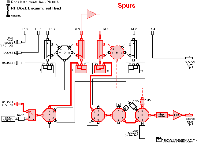
Test Head Configuration for Spectral Purity
The test configuration shown is a typical spectral purity measurement configuration for the RI 7100A’s RF Test Head. Please notice that the test configuration is the same as for making two port S parameter measurements but in high dynamic range instances the extra sensitivity of the direct receive path may be needed. To measure the spectral purity of the DUT shown, the system needs to measure the levels of the DUT’s transmitted signals into port RF6 at both the fundamental frequency and the harmonic frequency (or spur frequency). Both the transmitted fundamental and harmonic/spur signals are routed (as shown above) through the incident arm of the port RF6 directional coupler, the electronic switch which selects the incident arm, or direct through the coupler, through the low loss mechanical port direction switch, two more switches. Then either path goes through the final switch, a step attenuator, and a RF preamplifier to the single channel System Receiver (connected to port REC) for signal processing.

