The Cassini style test fixture requires the routing of RF signal from the Cassini test head to the Test Instrument Module or TIM attached to the tester. This document describes the physical steps required to produce this subassembly.
- RF Cable Kit (RIK0102A) + RF Block Kit (RIK0103A):
- After verifiying the required hardware bend one of the 4" semi-rigid cables to the length shown in "Bend 1". You may have to move the label to the center of the cable. You can use any tool to bend the cable as long as it makes a smoothe round bend (i.e around a nut driver).
- Bend the second 4" semi-rigid cable to the length shown in "Bend 2".
- The two bent cables should be as shown in "Bend Results".
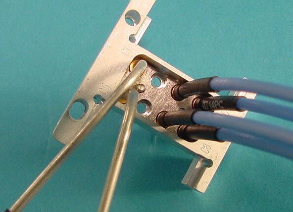
- Loosely install the two bent semirigid cables as seen in "RF Block 1". For the standard configuration, the higher cable should be in the C5 position and the shorter should be in the C1 position.
- RF Cable Kit (RIK0100A or RIK0101B)+ RF Block Assembly (RIK0143B):
- Install the flexible cables into one of the brackets as shown in the "Cable and Bracket 1" and "2" pictures.
- Assemble the four RF cables and the two semi-rigid cables into one assembly as shown on RF Block 2.
- Using the provided bracket, assemble the other end of the semi-rigid cables into the other RF block as shown in RF Block 3. The cable shortest cable (vertically) should go into position C7. The taller cable should go into C6.
- Place the cables and bracket assembly into the housing of the RF block (see pic. "Place in Block").
- Attach the assembly to the RF block using the 2-56x14" screws (M9C7X22A) as displayed in pic below ("Attach to Block").
- Insert the block from the top side of the plate (see pic. "Insert Block").
- Attach the block assembly to the fixture bottom plate with two 4-40x3/16" screws coated in Loctite (MC7SVE1A) as shown in pic below ("Assy to Plate").
- Example of Src/Receive block to RF TestSet block :
Below is an example of the standard configuration connecting the source and receive paths (via the #12F - #12F cables) to the RF testset block.

For reference of the testhead reources, please refer to the following document "Bottom Plate Assembly Resources - Cassini". 
|
|

