In order to calibrate the RI8607 50 GHz TestSet TIM, a Keysight N1913A Power Meter with a Keysight N8487A Power Sensor must be installed (see RIK0313A), along with a compatible 50 GHz Diag/Cal Interface plate. Prior to calibration, a '.gzp' with the CalKit Definition and Power Sensor calibration data must have been imported into Guru with Guru Browser. The Pmeter77GHz instrument and sensor data, Cal/Diag Fixture, and Cal Kit has to be activated before the default Cal Exec is opened and TIM specific calibration performed. Calibration test plans require the latest software, even if a different ShortCut is used in production.
Update 2023-05: filterGain calibrations added to improve relative measurements using different filter settings. (Requires Cassini Patch 332 TH50 and 338 Receiver)
IMPORTANT: Pay close attention to the Instrument Name and GPIB Address (step 8.6). The default values are NOT used.
To Activate the Power Meter:
- Connect the power sensor to the power meter.
- Confirm that the power meter is set to the correct AC voltage (120/220) and connect the power meter to the AC mains.
- Connect the power meter's GPIB cable to the tester's GPIB instrument pod. (If a GPIB handler pod exists, do NOT connect to the handler pod.)
- Turn on the power meter.
- Ensure the power meter is set to the correct GPIB command set:
- On the power meter, press the System button.
- Choose Remote Interfaces > 2 of 2 > Command Set > If it is not HP437B, select HP437
- Ensure the power meter is set to the GPIB address 20 as follows:
- On the power meter, press the System button
- Choose Remote Interfaces > GPIB Address > 20. If it is not '20' then manipulate to the GPIB Address enter 20 and then press Enter.
- Press the Display button to change the Power Meter back to display the power level measured, .
- Connect the Power Sensor, through the N-to-2.4 adapter, to the power meter's cal port and zero-cal the power sensor as follows:
- Press the Cal button (on the far right of the power meter).
- Select Zero + Cal
- Add the power meter to the tester's configuration as follows:
- On the tester, if the main Cassini window is not already open, choose ShortCut and select the latest from the list.
Note: Calibration test plans require the latest software, even if a different ShortCut is used in production. - Open a configuration panel by choosing System > Tester from the main Cassini window.
- In the configuration panel's menu, choose Instrument > Add GPIB Inst...
- Choose Hp437B then choose Select.
- The system will prompt for an Instrument Name. Enter Pmeter77GHz (case sensitive) and press OK.
IMPORTANT: Instrument Name is case sensitive, enter it exactly as show with Upper Case "P", "G", and "H".
Note: While the instrument is named Pmeter77GHz, it can only measure up to 50 GHz with the Power Sensor that is attached.
Prompt Before with Default Value (Pmeter)

Prompt After Typing "77GHz"

- The system will prompt GpibAddress for Pmeter77GHz, enter 20 and choose OK.
Prompt Before with Default Value (16)

Prompt After with Standard Value (20)

- Import Calibration Data for the mmWave power sensors:
- In the configuration panel, highlight the Pmeter77GHz.
- Choose Instrument > Calibration > Import from the Configuration Window menu, then choose Yes from the Please Confirm prompt.
- Highlight the appropriate N8487A sensor in the list based on the Serial Number and choose Select.
- Latch the Cal/Diag plate on the tester by placing the plate on the testhead and twisting the Fixture switch to Latch.
- Perform a system check by choosing System > Check from the main Cassini window.
- Confirm the Fixture appears in the configuration window.
To Prepare the Cal Kit Definition:
- Choose a cal kit by choosing Instrument > Add Cal Kit from the Configuration window.
- Choose the proper Cal Kit from the list. (example "CalKit_<CustID>_2-4mm_Term_<TermSN, i.e. DF##>")
- Confirm the CalKit appears in the Configuration window.
Loading the Tester's default Cal Exec:
The correct cal list is dependent on the configuration and the preferred access method. It may be different for each tester configuration. Typically, if you have a cal list for your tester, the necessary cals will be in that list. See Changing the Default Cal/Diag List Associated With a Cassini Tester for steps to change the default or select a temporary one.
- Choose System > Tester to open the Configuration window.
- Choose Tester > Calibrate to open the default Cal Exec.
Calibrating the RI8607 50 GHz Test Set:
Update 2023-03: Linearity Cal plans have been split into three pieces; "X1" (<20 GHz), "X2" (20-40.5 GHz), "X2 High" (>40.5 GHz) to prevent "out of memory" errors from occurring with tester configurations with a large number of instruments.
NOTE: Always run "Cal" and "Validate" test plans together. All 62 test plans must be run to have a valid Cal. If a Validate test plan fails, every selected test plan must be run again. This is the primary reason to select test plans in small groups. If the operator has to abort the Calibration procedure, choose System > Reset from the main Cassini window to reload the last valid calibration data before proceeding.
NOTE: Be sure all connectors are clean prior to starting the cal. The SSMP connectors from the TIM to the fixture, and the 2.4mm connectors at the test interface are particularly sensitive. Failure to ensure clean connectors will result in poor calibration results.
NOTE: When connecting to the 2.4mm connectors on the cal plate, the connector should be torqued between 8 lb-in (0.9 Nm) to 12 lb-in (1.3 Nm). Too little torque will result in poor calibration results. Too much torque might damage the connector.
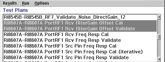
Select the first RI8607A calibration, 'RI8607A PortRF1 Rcv filterGain Offset Cal' and its associated 'RI8607A PortRF1 Rcv filterGain Offset Validate'. Choose Run > Selected.
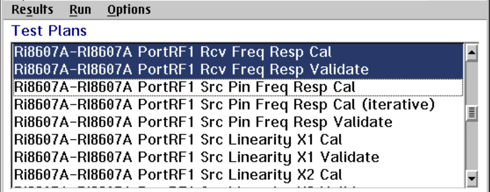
Next select 'RI8607A PortRF1 Rcv Freq Resp Cal' and its associated 'RI8607A PortRF1 Rcv Freq Resp Validate'. Choose Run > Selected.
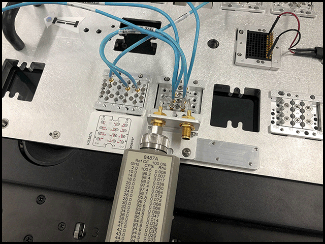
When requested, connect the RF Power sensor to the 2.4 mm connector at PortRF1 (C8) of the 50 GHz TIM.

NOTE: The message window may display multiple "SystemMenu - reset, to abort" messages while the PMeter is waiting for a signal while measuring very low power levels. No user intervention is required.
NOTE: The next calibration test plans will require the same connection to the Power Meter. Please do not change anything while running.
Hint: Each time they run, if the validate fails, note the 'Prelim src max' and 'Prelim src min' values. If each subsequent run gets them closer to zero then they will eventually converge and pass. In that case, the plans should be run again. If those values are not converging, then something is broken and contact [email protected] for assistance.
Select the next 3, 'RI8607A PortRF1 Src Pin Freq Resp Cal', RI8607A PortRF1 Src Pin Freq Resp Cal (iterative)', and 'RI8607A PortRF1 Src Pin Freq Resp Validate'. Choose Run > Selected.
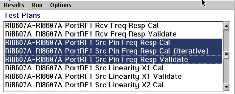
NOTE: Cal plans with "(iterative)" in the title may have to be repeated until its associated validate passes. On a TIM that has been previously calibrated, this is usually only 1 or 2 times. A TIM that has had its calibration reset, could require several repeats.
After the 'RI8607A PortRF1 Src Pin Freq Resp Validate' has passed, select the next calibrations and their associated validates. If you're confident the TIM is functional (or just feeling lucky), you can select all the way down to, and including, the 'RI8607A PortRF1 Src Freq Resp Validate'. A functional TIM will run all of these without requiring additional user intervention.
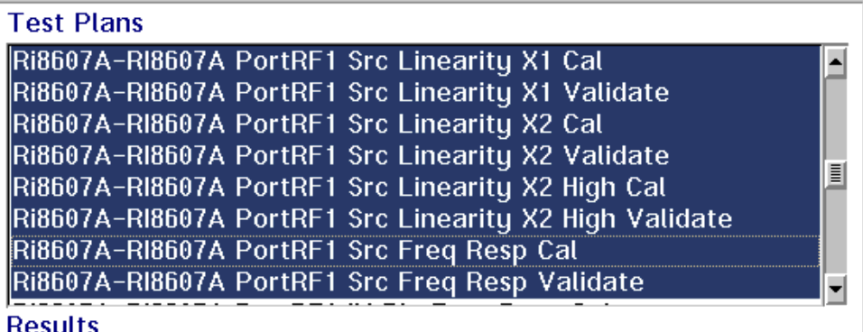
Select the next 3, 'RI8607A PortRF1 IM Pin Freq Resp Cal', 'RI8607A PortRF1 IM PinFreq Resp Cal (iterative)', and 'RI8607A PortRF1 IM Pin Freq Resp Validate'. Choose Run > Selected.
If the Validate does not pass, select the 'RI8607A PortRF1 IM PinFreq Resp Cal (iterative)', and 'RI8607A PortRF1 IM Pin Freq Resp Validate' and run until it passes. If the Validate fails, note the 'Prelim src max' and 'Prelim src min' values. If each subsequent run gets them closer to zero then they will eventually converge and pass. In that case, the plans should be run again. If those values are not converging, then something is broken and contact [email protected] for assistance.
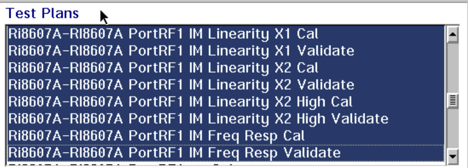
After the 'RI8607A PortRF1 Src Pin Freq Resp Validate' has passed, select the next calibrations and their associated validates. Select all the way down to, and including, the 'RI8607A PortRF1 IM Freq Resp Validate'. A functional TIM will run all of these without requiring additional user intervention.
When finished, select the next two calibration steps, "RI8607A PortRF1 ea Cal" and its associated validate, and click Run > Selected. This cal uses the 2.4 mm open/short/load.

When requested, connect the open to PortRF1 of the TIM as seen on the picture. Choose OK to proceed.

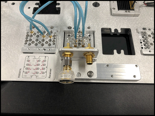
When requested, connect the short to PortRF1 of the TIM. Choose OK to proceed.

When requested, connect the Termination to PortRF1 of TIM. Choose OK to proceed.

When the validate test plan runs, the operator is requested to connect the Termination. Do not change anything, leave the termination connected. Choose OK to continue.

When requested, connect the short to PortRF1 of the TIM. Choose OK to proceed.

The next 33 test plans deal with PortRF2 Calibration and Validation. The exact same process described above should now be run on PortRF2. All the prompts will be the same, except they will show PortRF2 as shown.
If you're confident the TIM is functional (or just feeling lucky), you can select all the way down to, and including, the 'RI8607A PortRF2 IM Freq Resp Validate'. A functional TIM will run all of these without requiring additional user intervention.

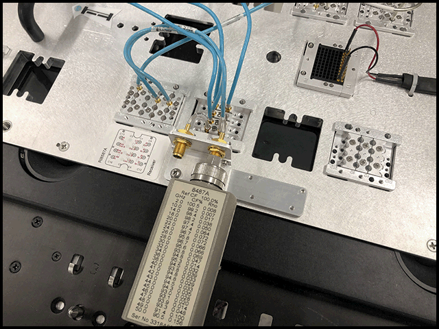
After the last validation test plan completes with a state of "Pass", the Calibration procedure is complete.

