

In order to calibrate the "V Band" RI8580B 50-70 GHz TestSet TIM (Testhead60), a Spanawave/Gigatronics Power Meter with 40 GHz Sensor1 and a Keysight N1913A Power Meter with a Keysight V8486A Power Sensor must be installed along with a Diag/Cal Interface plate with RIK0317A Block, 50-70 GHz Dual RR-15 V Band block in the correct location.
Prior to calibration, a '.gzp' with the CalKit Definition (ri.sys.ObjClass=RiCalKit) and Power Sensor cal data (RiInstrumentCal, ri.hw.Model=Hp437B) must be imported into Guru. This '.gzp' file is on the supplied USB stick or can be requested via an email to [email protected].
Steps to Prepare the Power Meters:
- Connect the power sensor to the power meter, for both the Keysight and the Spanawave power meters.
- Confirm that the power meters are set to the correct AC voltage (120/220) and connect the power meters to the AC mains.
- Connect both the power meter's GPIB cable to the tester's GPIB instrument pod, chaining either power meter into the next. (If a GPIB handler pod exists, do NOT connect to the handler pod.)
- Turn on the power meters.
- Add the Spanawave/Gigatronics power meter to the tester's configuration: (skip this step if it is already active)
- From the Configuration window, choose Instrument > Add Power Meter.
- Accept the default instrument name of Pmeter by choosing OK.
- Then accept the GPIB address of 13 and choose OK. Note that it is Roos' policy to always keep power meters at GPIB address 13. On the power meter, the remote light should flash on, then off. The Pmeter instrument should now be in the Configuration window.
- Ensure the Keysight power meter is set to the correct GPIB command set:
- On the power meter, press the System button.
- Choose Remote Interfaces > 2 of 2 > Command Set > If it is not HP437B, select HP437
- Ensure the Keysight power meter is set to the GPIB address 20 as follows:
- On the power meter, press the System button
- Choose Remote Interfaces > GPIB Address > 20. If it is not '20' then manipulate to the GPIB Address enter 20 and then press Enter.
- Press the Display button to change the Power Meter back to display the power level measured, .
- For each power meter, connect the sensor's N connector to the meter's cal port and zero-cal the power sensor:
- For Spanawave, press the Cal button (on the far right of the power meter)then choose Zero + Cal.
- For HP437B (Agilent), press ZERO then press SHIFT + ZERO to Cal.
- Add the Keysight power meter to the tester's configuration:
- On the tester, if the main Cassini window is not already open, choose ShortCut and select the latest from the list.
Note: Calibration Test Plans often require the latest software, even if a different ShortCut is used in production. - Open a Configuration window by choosing System > Tester button from the main Cassini window.
- In the configuration panel's menu, choose Instrument > Add GPIB Instrument menu.
- For the Keysight, choose HP437B then choose Select.
- The system will prompt for an Instrument Name, enter Pmeter77GHz (case sensitive) and press OK.
IMPORTANT: Instrument Name is case sensitive, enter it exactly as show with Upper Case "P", "G", and "H". - The system will prompt for a GPIB Address. Enter 20 and choose OK.
- Import Calibration Data for the Keysight Power Sensor:
- In the configuration panel, highlight the Pmeter77GHz.
- Choose Instrument > Calibration > Import from the Configuration Window menu, then choose Yes from the Please Confirm prompt.
- Highlight the appropriate sensor in the list and choose Select.
- Latch the Cal/Diag plate on the tester by placing the plate on the testhead and twisting the Fixture switch to Latch.
- Perform a system check by choosing System > Check from the main Cassini window.
- Confirm the Fixture appears in the configuration window.
Steps to Prepare the Cal Kit Definition:
- Choose a cal kit by choosing Instrument > Add Cal Kit from the Configuration window.
- Choose the proper Cal Kit from the list.
- Confirm the CalKit appears in the Configuration window.
- Verify the serial numbers match the items in the Cal Kit before starting by selecting CalKit form the list and choosing Instrument > Calibration > Inspect.
(See Calibration Kit Maintenance)
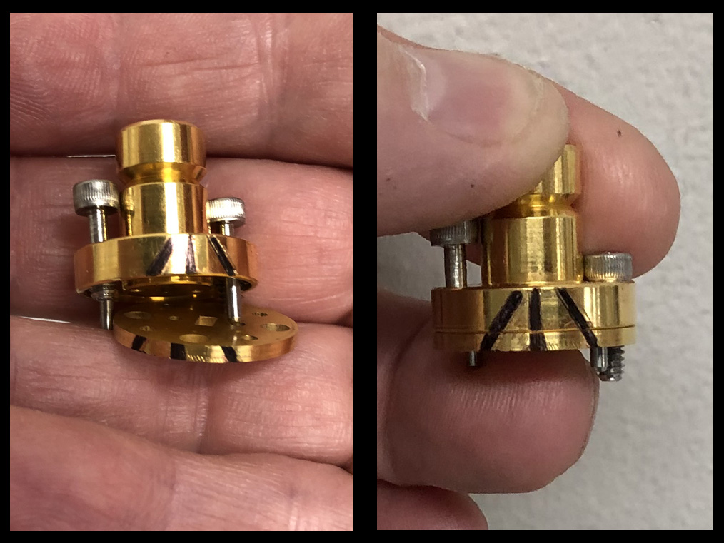
Figure 1: The 60 GHz TIMs may use the modified waveguide supplied with the 60 GHz Calibration Kit. (No longer required)
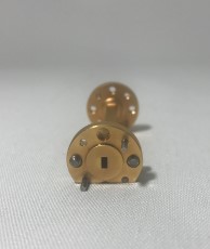
Figure 2: The 1.5 inch waveguide piece should remain permanently mounted to the power sensor and should be considered as part of the sensor.
Connecting waveguide
The screws on waveguide flanges are outside the waveguide projection. If not connected carefully, the waveguide connection can be tilted. This will result in improper calibration. When connecting waveguide flanges, tighten the screws progressively to keep the waveguide flat.
Also note that the cal plate block is flat without a waveguide boss. The cal kit's screws may bind if one is fully tightened before the other is started. Please start both screws about 1/2 way before tightening. This is particularly true for the screws on the short as they are longer than a standard screw, to account for the added thickness when the shim (offset) is inserted.
See Connecting Waveguide Flanges for more information. https://roos.com/docs/RBEH-CZXREV?Open
(Optional) Loading the TIM Cal List:
If the 60 GHz test set is permanently installed, then the TIM will be supported in the system Cal list and accessible from the Tester > Calibrate menu. If the 60 GHz TIM is transient (sometimes installed, sometimes not), then the Cals might be in a separate cal list.
To access the TIM Cal list:
- Choose System > Tester to open the configuration window.
- In the list of instruments, select the instrument called System and choose Calibration > Calibrate from the right mouse button menu or the Instrument menu.
- It will open a Choose a Calibration List window. (See Figure 2.1)
- Select "RI8580A 60 GHz TIM w Src1-2 Cal" from the list and choose select button. (See Figure 2.2)
Note: Do NOT save the Tester (Tester > Save) after loading this Cal List.
Calibrating the RI8580B 60 GHz Test Set:
IMPORTANT: Always run "Cal" and "Validate" Test Plans together. All 24 Test Plans must be run to have a valid Cal. If a Validate Test Plan fails, every selected Test Plan must be run again. This is the primary reason to select Test Plans in small groups. If the operator has to abort the calibration procedure, choose System > Reset from the main Cassini window to reload the last valid calibration data before proceeding.
NOTE: The exact cal plan names may be slightly different, depending on your tester's configuration. However the process is the same for all variants.
Select the first three calibration Test Plans and choose Run > Selected. These use the Pmeter instrument (Spanawave/Gigatronics) to calibrate the LO frequencies from 11.25 GHz to 18.75 GHz.
Select the next three calibration steps starting with "Ri8580B..." and choose Run > Selected.
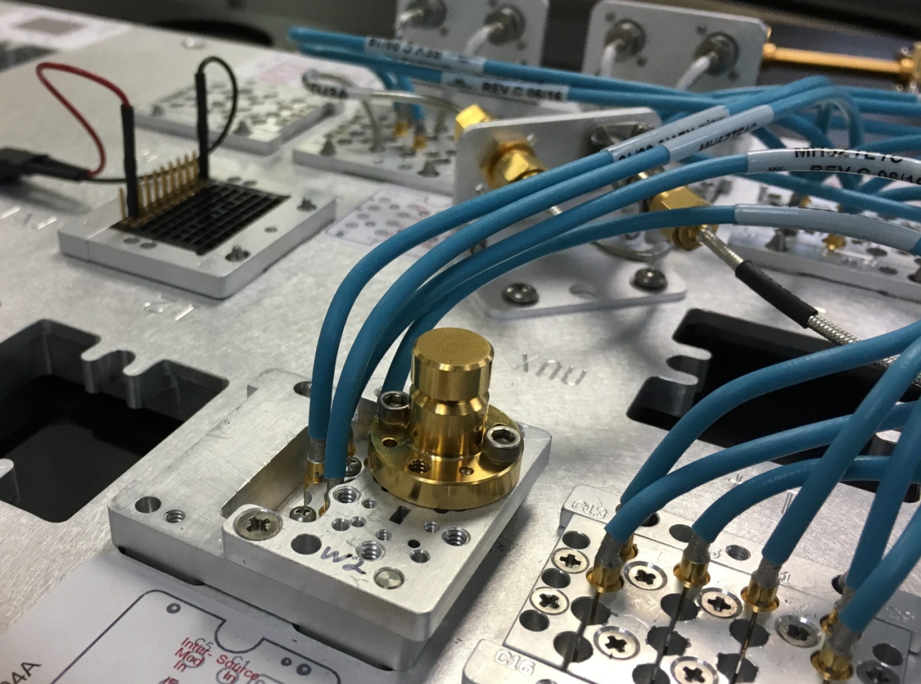
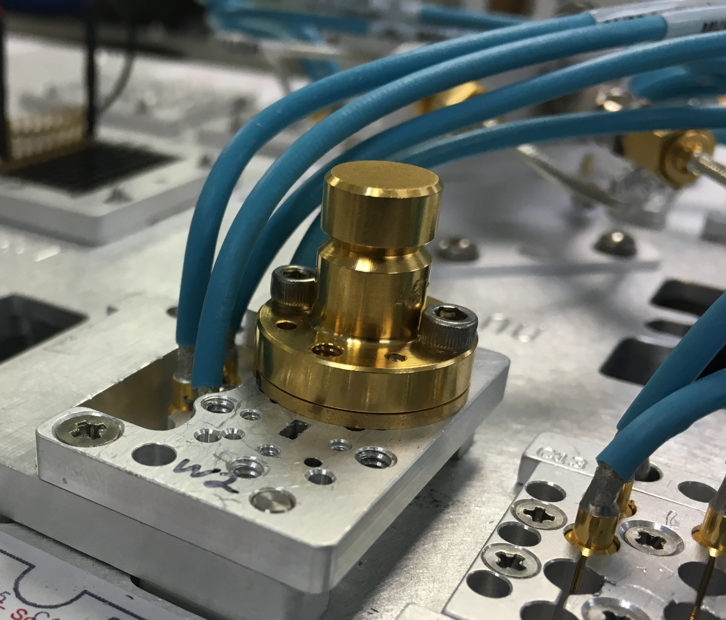
When requested, connect the RF Power sensor directly to Port W1 of the 60 GHz TIM.
Please mind the sensor orientation. The rectangular waveguide on the fixture block should align with the waveguide on the sensor. If the power sensor is turned 90 degrees, the waveguide will not be properly aligned and all calibrations will fail.
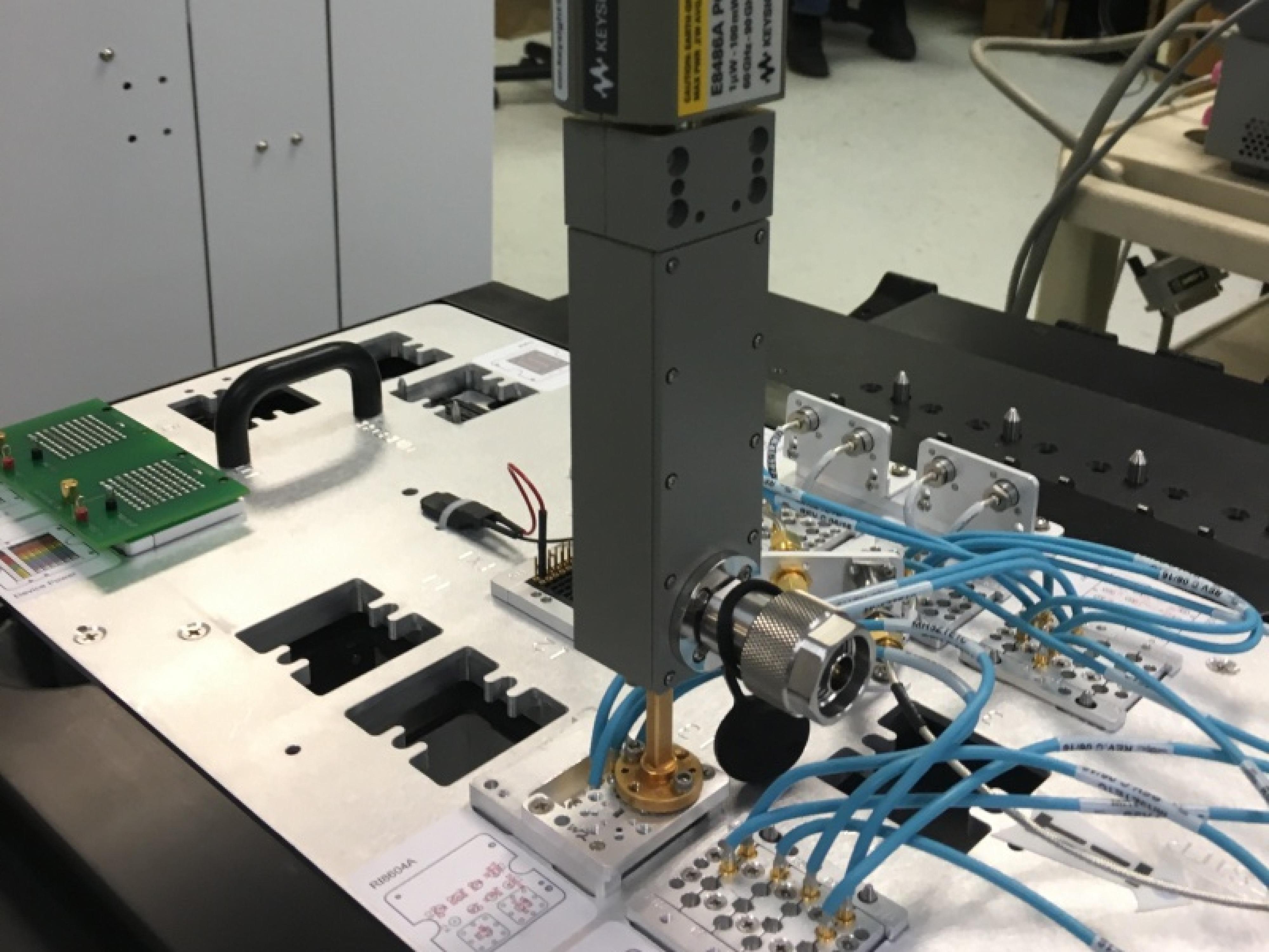
Attach the power sensor and choose OK to proceed.
Note: The next 12 calibration Test Plans will require the same connection to the Power Meter, please do not change anything while running.
When finished, select the next two calibration steps "... Port1 Rcv Freq..." and click Run > Selected.
When finished, select the next two calibration steps, "... Port1 Src Linearity..." . Click Run > Selected.
When finished, select the next two calibration steps, "... Port1 Rcv Frew Resp..." Click Run > Selected.
When finished, select the next four calibration steps, "... IM Src..." Click Run > Selected.
When finished, select the next four calibration steps, "... Port1 Src Atten...". Click Run > Selected.
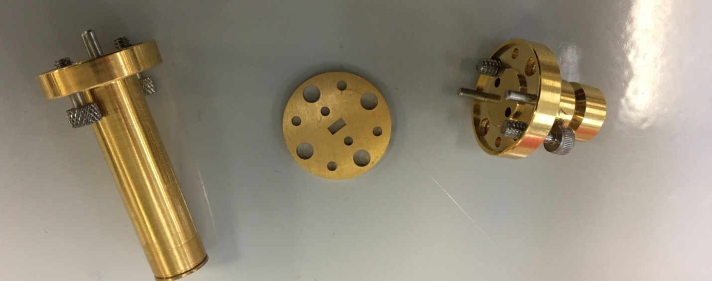
For the next Test Plans, the operator is asked to connect the Waveguide Cal standards for the EA Calibration and Validation.
Pictured (left to right): Termination, Offset, Short.
Select the next two calibration steps, "... Port1 ea Cal". Click Run > Selected.
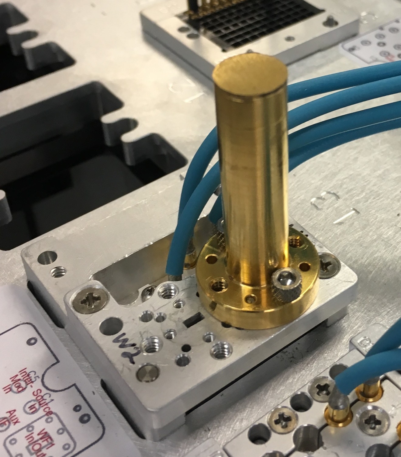
When requested, connect the Short to Port 1 of the 60 GHz TIM as seen in the picture below.
Choose OK to proceed.
When requested, connect the offset short to Port 1 of 80GHz TIM as seen on the picture. Note the addition of the 1/4 wavelength shim in the stack.
IMPORTANT: Check the orientation of the shim. Its rectangular waveguide must align with the Cal block's waveguide. If it is turned 90 degrees, then the Cal will be invalid.
Choose OK to proceed.
When requested, connect the Termination to Port 1 of 80GHz TIM as seen on the picture.
Choose OK to proceed.
When the '... Validate' Test Plan runs, the operator is requested to connect the Termination. The termination should still be connected, so do not change anything. Press OK to continue.
Next, the operator is requested to connect the 3/8 short (see Figure 16), press OK to continue.
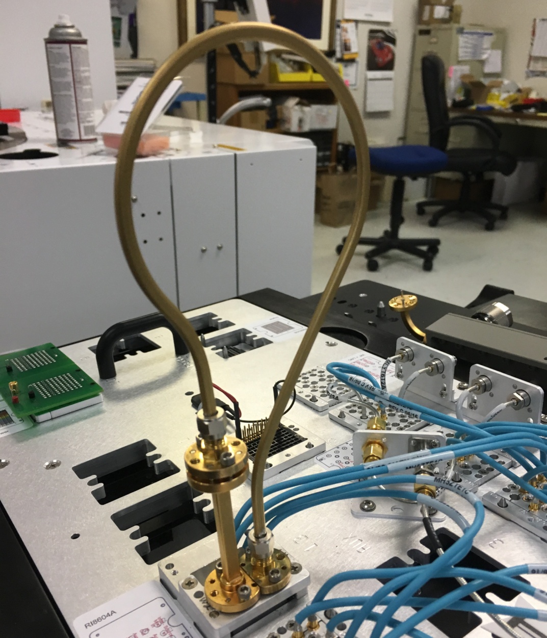
The next Test Plans deal with the Port 2 Calibration and Validation. The operator is asked to use waveguide loop to connect to either a TIM port or the power meter.
See Figure 21 and Figure 22 below:

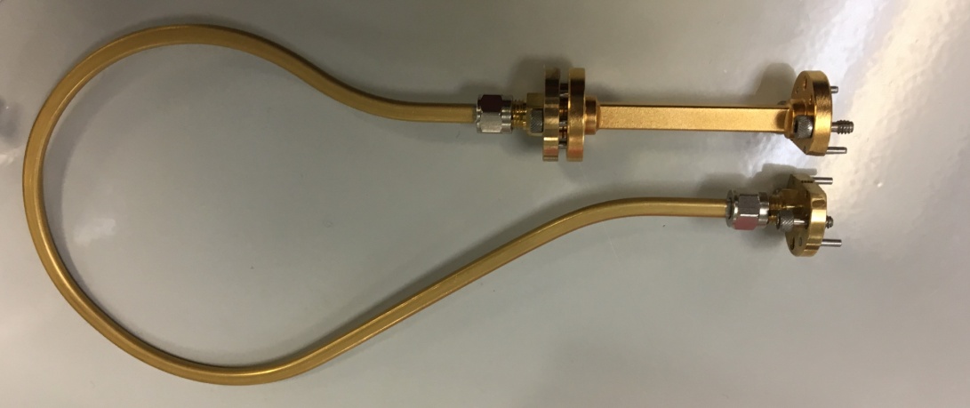
Select the final two calibration Test Plans (... Port2 Rcv Freq Resp...), choose Run > Selected
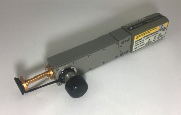
When requested, connect the RF Power meter, thru waveguide loop, to Port 1 of the 80 GHz TIM as seen on the photo below. Please mind the waveguide orientation so that rectangular holes should be connected from TIM port, to waveguide cables, to power meter sensor. Use an appropriate spacer under the power sensor so as to keep the loop properly oriented. Note that the plastic box for the cal standards can be used as an appropriate spacer.
Choose OK.
Next, the operator is requested to connect Port 1 and Port 2 using the same waveguide loop. Try to not flex the waveguide loop. Loosen the loop from the cal block to provide some flexibility, connect the thru line between the loop and the block, and tighten everything.

The last 2 Operator Requests of the Validation Test Plans require the operator to do the same 2 steps in reverse.
The Calibration procedure is complete after the last "... Validation" testplan completes with a state of "Passed".
If additional RI8508 TIMs are in the configuration, the steps above are repeated, but the Test Plan name is appended with TH60# (where # is 2, 3, 4, etc...).
Footnote 1: The TIM's frequency range is 50-70 GHz, however the calibration is 45-75 GHz. The LO is divide-by-4, so the LO is calibrated from 11.25 GHz to 18.75 GHz. This puts the LO spec range just inside of the 18 GHz sensor but the LO cal range just outside of the 18 GHz sensor. Since the sensor's performance does not drop quickly, it will work and not violate our spec.