THESE INSTRUCTIONS ARE FOR USE ONLY WITH EXPLICIT ADVICE FROM ROOS SUPPORT.
These instructions are to be followed to program a POD that appears as "Unknown Node" in the equipment pool to become a "Instrument" (GPIB interface only) , or a "Handler" or "Prober". This can happen if the "Header Version" number was changed during the
GPIB Instrument and Handler PODs can be identified by the model number (e.g. RI8502, RI8516, RI8517, RI8552, RI8579) and physical interface (Parallel, Serial, GPIB). GPIB Probers require a RI8579B Prober Pod and are controlled with the same communication system but are programmed differently, so for the rest of this document, the "Handler" will only be used. The RI8505 Instrument PODs are programmed differently and may require special drivers from Roos Instruments, contact [email protected] with brand/model information. The "B" versions are physically taller and include opto-isolation circuits to avoid communication issues with Handlers which are operating on a different ground plane, typically by connecting to a different power source.
WARNING: The "Module Browser" can be used to reprogram ANY instrument attached. USE CAUTION and DO NOT perform any changes without explicit direction below. Due to risk of accidental instrument reprogramming, DO not regularly change the settings to support two different handlers, instead, purchase two Handler Pods and leave them attached to the handler when connecting different test systems.
IMPORTANT: Only ONE (1) Handler Pod can be attached at a time. An additional GPIB Instrument Pod can be attached to control AUX instruments via a different GPIB cable/bus.
IMPORTANT: Only program one Unknown Node at a time. If multiple Pod types are connected, disconnect them all to avoid any confusion.
Steps to Initialize Handler Pod:
- Start with a running Cassini system (from the latest available ShortCut).
- Connect the pod using the supplied RIFL2 to RIFL3 cable to any available RIFL port on the side of the test head.
- Press System > Check from the main Cassini window to identify the recently attached Handler Pod.
- Press System > Equip > Nodes to open the Equipment Pool window. It should appear as "Unknown Node"
- From the Equipment Pool window select Nodes > Control Modules menu to open the Module Browser window.
- In the Module Browser window, in the left section, find and highlight the "Unknown Node".
- Select Node > Upgrade Base Def. (See Figure 2)
- Choose the correct model from the "Choose a Node to Copy" list and choose select. This is number is printed on the front of the Pod and on the Serial Number label (if present). (See Figure 2)
RI8502 GPIB Instrument Pod (not for handlers, but GPIB instruments like Power Meters or axillary Power Amplifiers)
RI8516 Serial Handler Pod
RI8517 Parallel Handler Pod
RI8552 GPIB Handler Pod
RI8579 GPIB Proper Pod - (Optional) If a Serial Number label is printed on the Pod, choose Node > Change Node Serial Number and type the correct 8 digit serial number at the "enter node serial number" prompt and choose OK. (See Figure 3 & Figure 4)
- In the Module Browser window, in the left section, find and highlight the Handler Interface Module
"YXXXXXXX Handler". The the "Handler" name could be the name of the configured handler ( i.e. SEIKO EPSON ). - In the top right section highlight "Handler RI#####". (RI#### is the model number of the Handler Pod).
- In the lower section enter the proper values for the Pod (polarity or timing) in the yellow boxes. ( See Handler Control Pod Configuration for each Pod type: Parallel, GPIB or Serial)
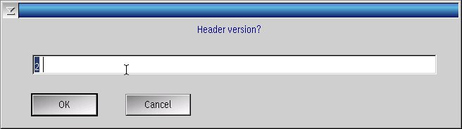
Caution: Do not change any of the default BIN assignment values. Bin assignments are handled by the Test Exec (program) and may be displayed in these settings for backward compatibility only. - After all changes have been made in the Module Browser window select Node > EE Save Node Info from the right mouse button menu. Choose Yes to confirm and DO NOT CHANGE THE HEADER VERSION when prompted, choose OK. Configuration is now complete. The Header Version is automatically detected by the system and describes the size and type of EEPROM memory is available. The configuration is stored in the Pod and does not rely on communication from the tester to load it's configuration. The EE-PROM has a limited number of writes (100,000). (See Figure 5 & Figure 6)
- Now disconnect the Pod from the RIFL port and perform a System > Check to remove the Pod. Reconnect the Pod and perform a second System > Check and confirm the settings are read properly from the Pod.
Figure 1: Upgrade Base Def menu selection
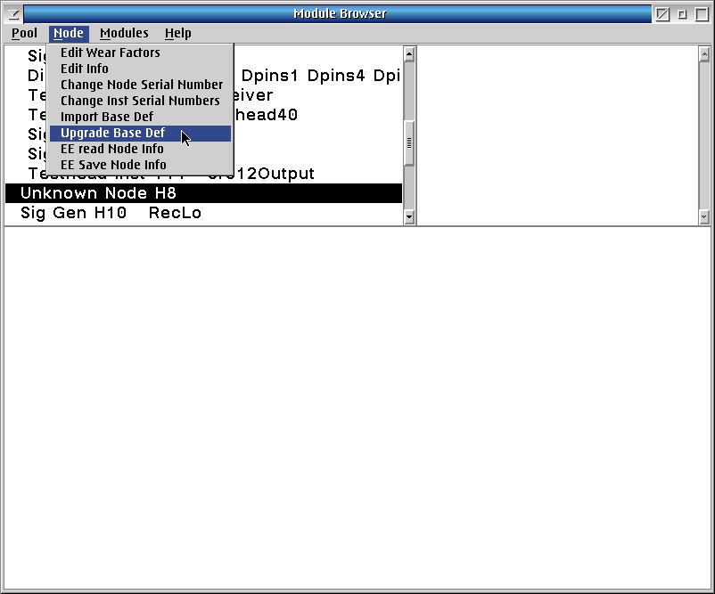
Figure 2: Choose a Node to Copy
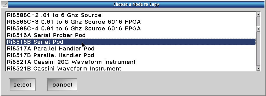
Figure 3: Change Node Serial Number (Optional)
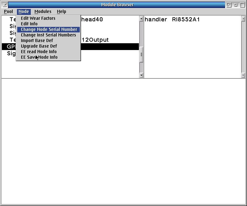
Figure 4: Enter Node Serial Number
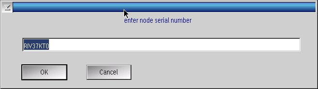
Figure 5: EE Save Node Info
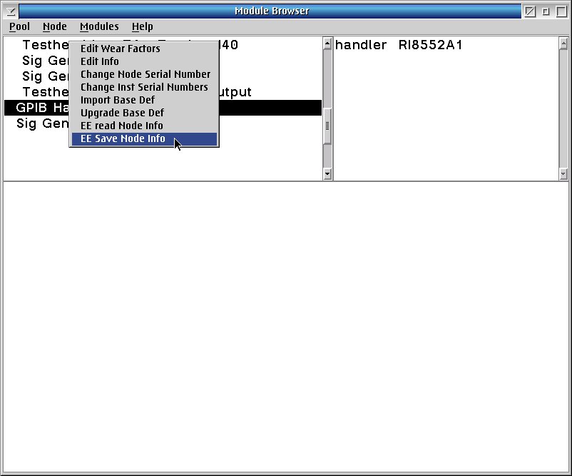
Figure 6: Header Version? (LEAVE DEFAULT VALUE)