

This item will not be restocked when depleted and should be avoided for new designs.
This product entered limited availablity on 01/05/2016.
View RIKs with Limited Availability for a complete list.
Suggested Replacement: RIK0266A; RIK0267A; RIK0263A
Expiration Reason: All PODs now have Opto-Isolation built-in and 15' RIFL cable included with RIK
Aditional replacements may be found by searching for RI8590A (change the REV letter) or Ground Isolator for Handler Pods.
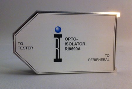
Ground Isolator for Handler Pods
Solves intermittant Cassini Handler Grounding Issues.
Part Number: RI8590A
Provides GROUND isolation that may affect handler communication. Only use if grounding problems are causing handler communication issues between CASSINI and the handler or prober. This could happen if the power supplying the handler/prober is "different" from the Cassini, causing a ground differential.
Note: Symptoms typically include "packet not sent" errors or handler interruptions. The best solution would be to resolve the ground differential issue. Try powering the handler and Cassini from the same plug. Verify the ground cable connects properly.
Install Opto-Isolator in between TESTER and SERIAL/PARALLEL/GPIB POD with the supplied RIFL cable. This assumes that a POD is already connected to the TESTER via a RIFL 2-3 cable and the peripheral. Make sure the POD is properly detected BEFORE attempting to attach the OPTO-ISOLATOR by performing a System | Check, then opening the System Browser and checking for the POD in the appropriate "H" port.
Simplified Diagram
[Tester] --> [Opto-Isolator]-->[Pod]-->Handler/Prober/Instrument
- Start with a POD connected from the "H" port of a Tester to the Handler/Prober/Instrument.
- Disconnect RIFL cable that connects "H" port on Tester from existing POD.
- Connect the existing RIFL cable from Tester to OPTO-ISOLATOR's "TO TESTER" port.
- Connect new RIFL cable from OPTO-ISOLATOR's "TO PERIPHERAL" port to the POD that is already connected to the device.
- The communication channel is now isolated from ground loops with an optical communication bridge. Contact Support for assembly instructions.
- IMPORTANT: Do not plug the RIFL cables into the wrong ports of the OPTO-ISOLATOR. Permanent damage to the OPTO-ISOLATOR can occur.