

The CASSINI (or RI7100C) ATE systems can operate in a wide range of environmental conditions. Depending on the system configuration, some specifications may not apply or have individual requirements. No special plumbing or ventilation is required. Customer must provide items designated with "NOT PROVIDED" label. All values are subject to change without notice.
- Height: 1,745 mm (68.7 in.)
- Depth: 1,151 mm (45.3 in.)
- Width: 843 mm (33.2 in.)
- Max Shipping Weight: 250 Kg (550 lbs.)
- Electrical Plug: NEMA 5-20P Plug Provided (Cassini side is IEC320-C19)
Other Plug Types: Cut off NEMA provided plug and use pig-tail plug adapter. NOT PROVIDED - 20 AMP service
- Minimum: 0.15 kVA
- Maximum: 0.75 kVA
- Aux Rack Maximum: 1.2 kVA (300 VA per Source)
| Function | Label | Color, IEC |
| Protective Earth, Ground | PE | green-yellow |
| Neutral | N | blue |
| Line, single phase, Hot | L | brown or black |
- Height: 0.256 m (10.08 in.)
- Depth: 1.056 m (41.61 in.)
- Width: 0.754 m (29.72 in.) Includes TIMs
- System Weight: 79 Kg ( 174 lbs.) (8 TIMs)
- Max Shipping Weight: 105 Kg (230 lbs.)
- Electrical via 48V AC-DC Power Adapter:
- IEC320-C13(f) [PSU side is IEC-320 C14(m)]
- Input AC Power Requirements: 3.8A/115VAC or 2A/230VAC
- Max Inrush Current: 95A/115VAC or 120A / 230VAC
RI8591A "Cassini SPYDER" Infrastructure:
- Height Min/Max: 741.9/1097.3 mm (29.2/43.2 in.)
- Depth: 576.3 mm (22.7 in.)
- Width: 772.7 mm (30.4 in.) Includes TIMs
- System Weight: 79 Kg ( 174 lbs.) (8 TIMs)
- Typical/Max Shipping Weight: 32/45 Kg (70/100 lbs.)
- Electrical:
- Plug type: NEMA 5-15P (Cassini side is IEC320-C13)
- Minimum: 0.15 kVA
- Typical: 0.40 kVA
- Maximum: 3.6 kVA (IEC C13 pass through)
- Input voltage and frequency ranges supported automatically.
- 220 V or 110 V
- 50 Hz or 60 Hz AC, Single Phase Sine-wave input.
Fixture: (for docking with a Handler or Prober)
- Always consider the Fixture height when determining minimum clearance of the Test Head.
- Height: 195.6 mm (7.7 in.) - includes clearance for alignment pins (Varies based on Model/Design)
- Depth: 266.7 mm (10.5 in.)
- Width - 16 slot test head: 558.8 mm (22 in.)
- Force air option may be included, documentation provided separately.
Environment:
- Operating Air Temperature: 10° to 35°C (50° to 95°F)
For best calibration performance, a consistent ambient room temperature of ± 5°C is recommended. - Humidity: 8% to 80%
- Docking options based on Handler/Prober Type: Hard dock (RIK0070A, HNDPLATE), Soft dock (Cables)
- Handler "Pod" per handler/prober per system: GPIB (RIK0263A), Serial (RIK0266A), Parallel (RIK0267A) - N/A for RI8611A
Requires factory RI configuration and programming, send detailed handler control logic to "[email protected]" prior to ship date. - Handler Pod Interface Cable: Parallel 25 Pin Female D-Sub (Custom MFSHLX1A), Serial Female RS232, or GBIP cable. NOT PROVIDED
IMPORTANT Electrical Ground With Handler/Prober:
- Facility should maintain the same ground at the facility between the Handler/Prober supply and the Tester supply.
The green ground wire in the side/back of the Infrastructure can be connected directly to the handler ground. This should be inspected each time a handler is connected to the test system by the operator.
Note: RI8611A "Cassini V93K CTH" Infrastructure does not require Handler ground cable. - The ground should be checked each time a Handler/Prober is first connected. Measure both AC voltage (must be less than 50 millivolts) and ground resistance (which should be less than 5 ohms) between the tester ground and the handler ground.
Note: Measuring negative resistance is a sign that DC or AC voltage is present. Any of these conditions would indicate failure to ground and should be corrected prior to testing parts.
It is essential to maintain solid ground between the handler and the infrastructure. This helps to prevent Device Under Test (DUT) damage and damage to the RI handler interface Pod.
- Surface not needed for Cassini 16 (RI8568B) with Aux Rack, Touch UI (RI8583A) or Arm UI (RI8599A) or Cassini V93K CTH (RI8611A)
- System Controller EPC TIM or Linux NUC requires standard CAT-5 RJ45 ethernet network cable to integrate with network and access Guru Server.
- Monitor requires a facility power plug (varies based on monitor C13 or C7). If available, can be supplied by RI8568B's AUX rack.
- Workspace (cart) is needed to hold monitor, keyboard and mouse. NOT PROVIDED
- Workspace must be located within Keyboard/Mouse/Video cable reach of the System Controller or USB RIFL Master (adjacent to system)
- Input Pressure 65-120 PSI (regulated to 90 psi)
- System Connector Type: Quick Disconnect US Industrial/Milton MIL-C-4109 Male (preferred)
4109 Male @ Facility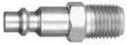 Cassini System
 - Adapters included with system: (MPSNYT5A)
- THREAD NPT 1/4" Female @ Facility to Quick Disconnect on tester (option #1)
Facility 1/4" NPT thread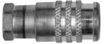 System Connector
 - HOSE 8mm or 5/16 in.: Barbed hose adapter and clamp with 1/4" NPT male thread (option #2)
Hose @ Facility
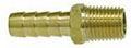 Adapter to Cassini System (thread)
Additional information:
| Cassini Footprint - Cassini 16 Infrastructure | |
| Cassini Footprint - Cassini SPYDER 8 Infrastructure Cassini Footprint - Cassini V93K CTH Infrastructure |