DIB Switch Driver controls TTL logic with 48 pins and can be used as either an Instrument or with Fixture Path Switch commands (not both).
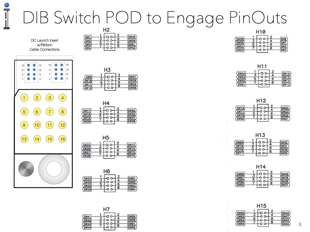
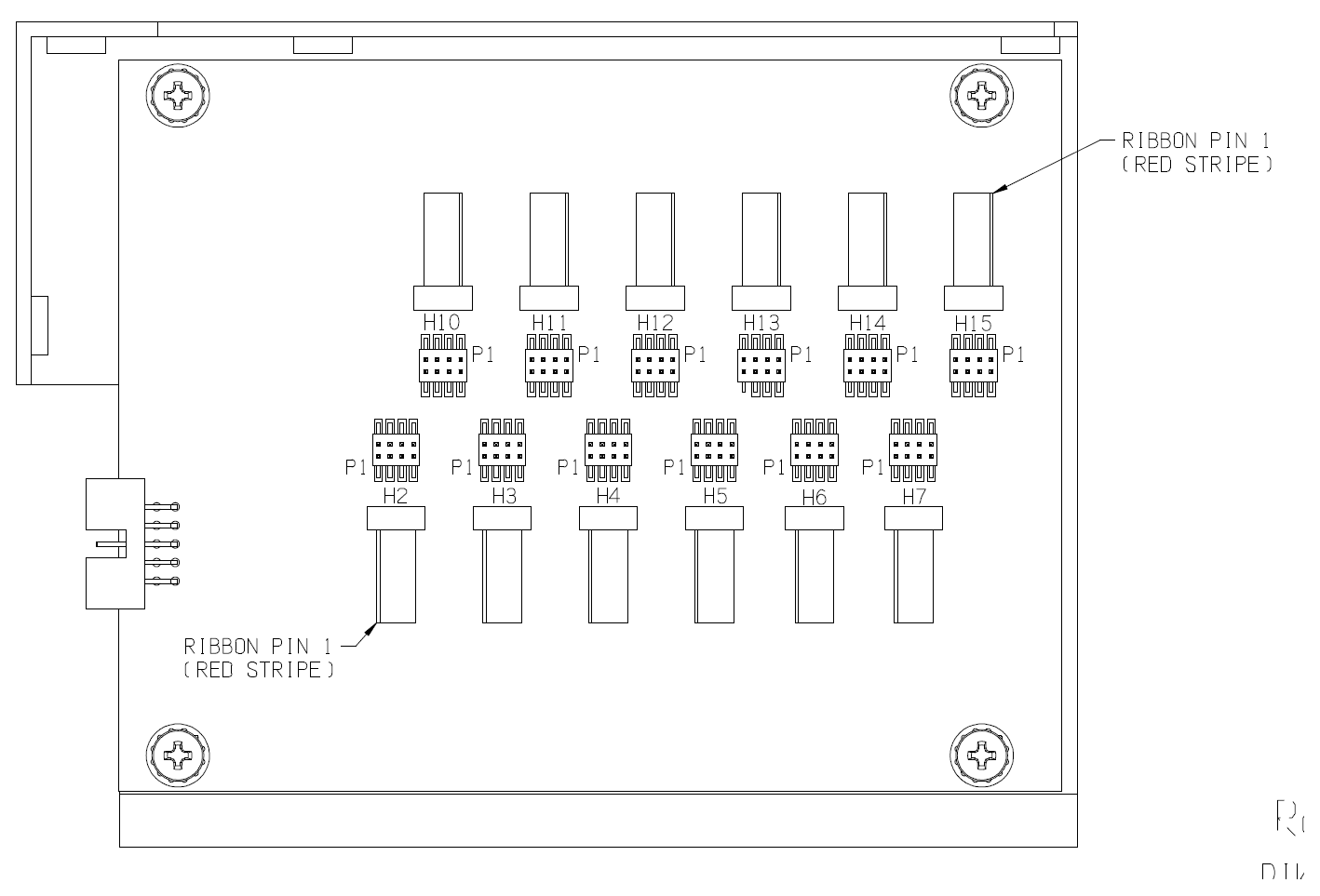
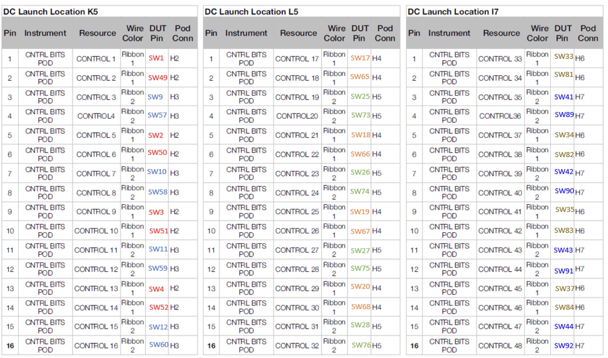
Connects to Fixture mounted components, DIB or TopHat via Ribbon provided with RIK0309B Engage DC Insert, 16 Pin 2x4 Header & Ribbon to access any Pod install location.
Requires
POD board labeled as "FEA1"
Related Documents:
User account required Create new accountProgramming Guide pending - contact [email protected] for details.
This POD can be controlled with Fixture Instrument (Module) or as a MEMSDriver1 Instrument when added to a Fixture Definition with the Device Connection Editor. The Fixture Instrument does not have access to some features like Reset, Clock Mode, Measure Pin, etc.
- To Add MEMSDriver1 Instrument to the Fixture Def:
- Choose Apps > Device Connection Editor.
- Choose Fixture tab.
- Choose Dev Con > Load Fixture... and select the target Fixture Def.
- Choose Dev Con > Edit Instruments...
- Choose Add from the right mouse button menu on the Instrument ID pane on the left.
- Choose Ri74503A MEMS Driver and choose OK.
- From the moduleMap drop down list, choose the M# location that matches where the Pod is installed. (i.e. if the Pod is installed in slot 1, choose M1).
- Choose OK to close the Editing Instruments window.
- Choose Dev Conn > Save Fixture, increment Version, and OK to Save the Fixture Def.
- Assign a Fixture ESN to this Definition with Fixture and DIB: assigning a new physical item with an ESN to a Definition file https://roos.com/docs/TDOO-C54NRB
- When a Fixture that is associated to this FixtureDef is activated, a MEMSDriver1 instrument appears in the configuration and can be used in a testplan from an Tester Edit panel (Tester > View) or manually controlled from the Control panel (Tester > Control).
- To Add Fixture Module to the Fixture Def:
- Choose Apps > Device Connection Editor.
- Choose Fixture tab.
- Choose Dev Con > Load Fixture... and select the target Fixture Def.
- Choose Dev Con > Edit Modules...
- Choose Add from the right mouse button menu on the pane on the left.
- Choose RIK0296A and choose OK.
- From the Location drop down list, choose the M# location that matches where the Pod is installed. (i.e. if the Pod is installed in slot 1, choose M1).
- Choose OK to close the Editing Instruments window.
- Add "Switch Action Command" to any Fixture Path. Remember to set the default idle state that the Fixture will return to when not in use.
- Choose Dev Conn > Save Fixture, increment Version, and OK to Save the Fixture Definition (RiFixtureDef). (Reference Switch Action Commands)
- Assign a Fixture ESN to this Definition with Fixture and DIB: assigning a new physical item with an ESN to a Definition file https://roos.com/docs/TDOO-C54NRB
- When a Fixture that is associated to this FixtureDef is activated, a MEMSDriver1 instrument appears in the configuration and can be used in a testplan from an Tester Edit panel (Tester > View) or manually controlled from the Control panel (Tester > Control).
Switch Action Commands:
A5Sxx=1
A = Constant "A" for Action
5 = POD Location[1 - 8]
xx = switch number [01 to 96]
=1 ON
=0 OFF
A[1-8]Sxx=[1|0][;[1-8]Sxx=[1|0]...]
i.e. to set pod module at module address 5 pin 06 to 1
A5S06=1
i.e. to set multiple bits for a path, ex. module address 5 pin 06 to 1, pin 07 to 0, pin 08 to 1
A5S06=1;5S07=0;5S08=1
Examples:
A4S23=1;A4S24=1;A4S44=1 to switch ON Pins H12-4, H12-2, H7-7 on the MEMS board mounted in POD location 4
A1S1=1;A1S2=1;A1S3=1;A1S4=1 to switch ON Pins H2-1, H2-3, H2-5, H2-7
A1S1=0;A1S2=0;A1S3=0;A1S4=0 to switch OFF Pins H2-1, H2-3, H2-5, H2-7
TODO Note: alternate action string may be added that is similar to A5H4P5=1 for slot 5 header4 pin5.
Figure 1: Editing Instruments
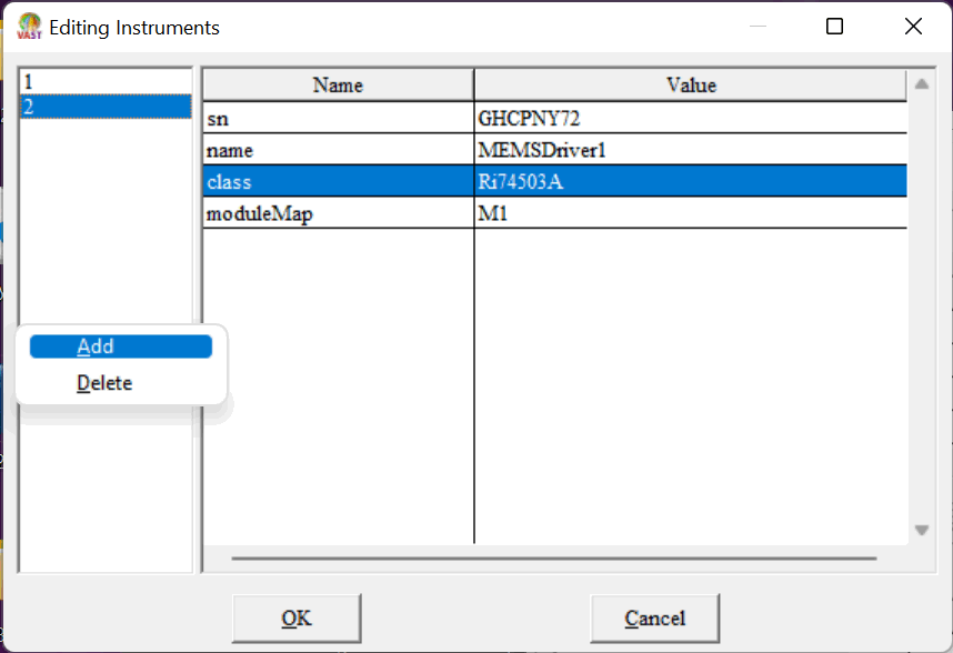
Figure 2: Selecting Ri74503A MEMS Driver
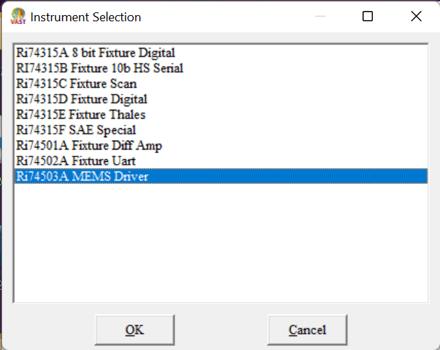
Figure 3: Viewer > MEMSDriver1
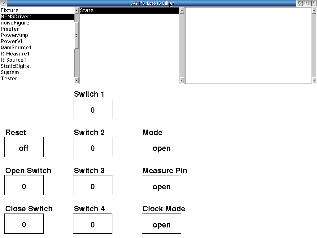
Reset: Set all drivers to open
Open Switch: open the switch arm (decimal value from 1 to 96)
Close Switch: close the switch arm (decimal value from 1 to 96)
Switch 1: program the switch. 0 is open
Switch 2: program the switch. 0 is open
Switch 3: program the switch. 0 is open
Switch 4: program the switch. 0 is open
Mode: Select mode for the data bus. (open, term, logic, meas)
Measure Pin: select pin pair to measure (open, C0, C1, F0, F1, D0, D1, D2, D3, D4, D5, D6, D7)
Clock Mode: Select mode for the clock pins (open, analog, digital)
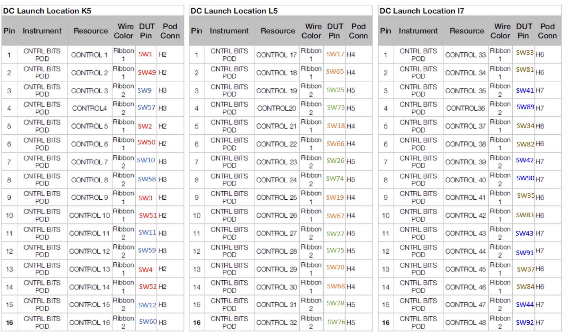
MEMS Switch POD
Contact Support for assembly instructions.


.jpg!OpenElement)
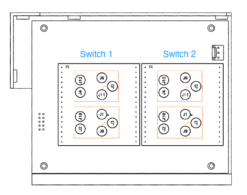
.jpg!OpenElement)
.jpg!OpenElement)
.jpg!OpenElement)
.jpg!OpenElement)
.jpg!OpenElement)
.jpg!OpenElement)
.jpg!OpenElement)
.jpg!OpenElement)
.jpg!OpenElement)
.png!OpenElement)
.jpg!OpenElement)
.jpg!OpenElement)